
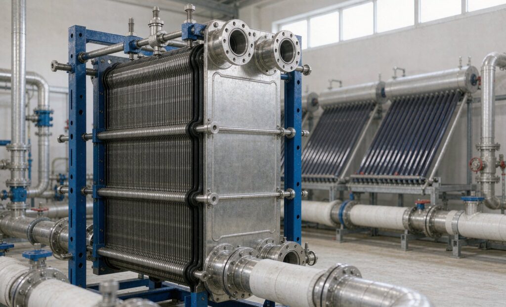
What a Solar Thermal Heat Exchanger Actually Has to Do
A solar thermal heat exchanger is not a boiler economiser with a different duty sheet. It sits between a collector array whose output swings with the weather and a storage tank that must hold a usable temperature overnight, and it does that across a temperature difference of only a few kelvin. Almost every underperforming solar hot water or solar process heating system we are asked to look at traces back to this component being sized as an afterthought — bought on price, selected on a nominal duty, and never checked against the real approach temperature the collectors need.
The distinction matters commercially. In an indirect system the exchanger is the only place where the collector loop and the stored water meet, so its performance sets the collector inlet temperature, and collector inlet temperature sets collector efficiency. A unit that is one or two kelvin worse than it should be does not fail; it quietly returns less heat every sunny hour for twenty years, and the owner blames the panels.
This guide covers the two exchangers present in a typical indirect solar system, the three numbers that govern their selection, the glycol and stagnation conditions that break units designed for clean hot water, and the checks worth putting in a specification before a purchase order is raised.
The Two Heat Exchangers in Every Indirect System
Most commercial solar thermal installations separate the collector fluid from the draw-off water. That separation is deliberate: it allows antifreeze in the collector loop, it keeps potable water out of a roof-mounted array, and it lets the collector side run at a pressure and chemistry the tank cannot accept. The cost is two heat transfer steps instead of one.
Collector loop to storage: the exchanger that governs yield
This is the unit that matters for performance. It takes propylene glycol at anything from 20 °C on a winter morning to stagnation temperatures on a summer afternoon, and it has to deliver that heat into the bottom of the storage tank without lifting the returning glycol temperature more than a few kelvin above the tank’s cold layer.
Two configurations are common. An external plate exchanger in the plant room is easier to service, easier to isolate, and can be sized independently of the tank. An internal coil or tank-in-tank arrangement avoids a pump and a set of pipework but is difficult to clean and effectively fixed for the life of the vessel. Below roughly 30 m² of collector area the internal coil is often acceptable; above that, an external unit almost always wins on both cost and serviceability.
Storage to load: the exchanger nobody specifies properly
The second unit transfers heat from the solar preheat tank to the domestic hot water, process loop or space heating circuit. Here the constraint is different. Domestic hot water service demands a double-wall barrier in many jurisdictions where the heat transfer fluid contains inhibitors, and double-wall construction costs surface area. If the specification simply says “plate heat exchanger, 60 kW”, the supplier will deliver a single-wall unit that meets the duty and fails the inspection.
A practical rule for this second unit: size it so that the solar tank can still deliver its design outlet temperature when the draw-off is at maximum simultaneous flow, not at the average. Simultaneous shower and process demand in a hotel, a hospital or a food plant routinely hits 1.5 times the hourly average, and that is the condition in which recovery appears to fail.
Sizing the Solar Thermal Heat Exchanger: Three Numbers
Everything downstream of these three figures is arithmetic. Everything upstream of them is guesswork, which is why so many solar exchangers are wrong.
| Input | How to establish it | Typical value and why it governs the design |
|---|---|---|
| Peak collector output | Aperture area × peak irradiance × optical efficiency, then de-rated for incidence angle and dirt | Roughly 600–750 W per m² of aperture at design conditions. A 20 m² flat-plate array lands near 13–15 kW. This is the duty the exchanger must pass, not the average daily output. |
| Approach temperature at design | Required collector return temperature minus tank cold-layer temperature | 3–5 K. Every additional kelvin raises mean collector temperature by half a kelvin and costs roughly 1–2% of annual collector yield. |
| Storage volume and stratification | 50–75 litres per m² of collector aperture for domestic hot water; 60–80 litres per m² for space heating with a buffer | Sets the flow rate through the primary side and therefore the pressure drop available to the exchanger. |
The approach temperature is where most selections go wrong. A supplier quoting a standard unit at 10 K approach will meet the thermal duty on paper, and the array will then run with a mean collector temperature 5 K higher than the designer intended. On a flat-plate collector with an efficiency slope of around 4 W/m²K, that is 20 W/m² of lost output at design — 400 W on a 20 m² array, every hour the sun shines. Over a year in a moderately sunny climate that is a measurable fraction of the whole system’s yield, and it was decided by a line on a datasheet.
There is a genuine trade here. Tightening the approach from 5 K to 2 K increases surface area, pressure drop, or both. The right answer is usually a plate exchanger with a moderate chevron angle and one more plate than the thermal calculation strictly requires, accepting 15–20 kPa on the primary side. Solar loop pumps are small and run on PV or mains at low load; the exchanger’s pressure drop is rarely the binding constraint. Collector yield is.
Glycol, Stagnation and the Conditions That Break Standard Units
A solar loop is a harsher environment than its temperatures suggest. Three conditions separate a unit that lasts from one that does not.
Glycol degradation is a chemistry problem, not a temperature problem
Propylene glycol at 30–40% concentration protects to roughly −15 to −20 °C, which covers most of Europe, northern China and North America. It also oxidises. Over time, and faster at stagnation temperatures, glycol degrades into glycolic and other organic acids. The fluid’s pH falls, the acid attacks copper brazing and aluminium, and the resulting sludge deposits preferentially in the narrowest passages available — which in a plate exchanger means the channels.
Two consequences for selection. First, if the unit is brazed copper, the glycol side is its weak point and fluid testing is not optional; pH and reserve alkalinity should be checked every six months and the fluid replaced on the manufacturer’s schedule rather than when it turns brown. Second, any exchanger with a gasketed glycol side needs gasket material rated for the acid condition, not just the temperature. EPDM handles typical inhibited propylene glycol well; NBR does not handle the degradation products.
Stagnation is a design case, not an accident
When the pump stops on a full tank on a clear summer day, the collector sits in the sun with no flow. Flat-plate absorbers reach 150–180 °C; evacuated tubes exceed 200 °C. The exchanger is not at that temperature, but the pipework and the first few plates of a directly connected unit see a slug of very hot, partially vaporised fluid when the pump restarts.
The standard mitigations belong in the system design rather than the exchanger specification: a drain-back or drain-down arrangement, a heat dump, or a controller that restarts the pump at a temperature below the fluid’s degradation threshold. What the exchanger specification must state is the maximum working temperature and whether the unit will see two-phase flow at any point. A unit selected for 95 °C service and installed on a loop that stagnates at 170 °C will fail at a gasket or a braze, and the warranty discussion will be about the specification sheet rather than the equipment.
Hard water on the potable side
On the storage-to-load exchanger, scale is the dominant long-term risk. Above roughly 60 °C, calcium carbonate comes out of solution on the hottest surface, which is the exchanger’s hot inlet. A unit with a 5 K approach runs cooler than one with a 2 K approach and therefore scales more slowly — one of the few cases where a looser approach is the better engineering choice. Where water hardness exceeds about 200 mg/l as CaCO₃, specify a unit that can be opened for cleaning rather than a sealed brazed block.
Plate or Shell and Tube for Solar Duty
Both configurations are sold into solar thermal, and both can work. The decision usually comes down to approach temperature, water quality and whether the unit will ever need to be opened.
| Criterion | Gasketed plate | Brazed plate | Shell and tube |
|---|---|---|---|
| Achievable approach | 1–2 K | 1–2 K | 5–10 K in a single pass |
| Footprint per kW | Smallest | Smallest | Three to five times larger |
| Dismantle for cleaning | Yes, in place | No | Bundle withdrawal or chemical clean |
| Pressure limit | Typically 16–25 bar | 25–30 bar | Limited only by wall thickness |
| Glycol volume held | Low | Low | High — a real cost at fluid prices |
| Best fit | Large arrays, hard water, units that must be opened | Sealed closed loops, clean water, tight plant rooms | High pressure, dirty water, steam-backed or very large duties |
For a typical commercial array between 20 and 200 m², a gasketed plate unit on the collector loop is the default and a brazed unit is acceptable where the loop is sealed and the fluid is monitored. Shell and tube comes into its own on the storage-to-load side of large district or process systems, where the pressure ratings and the tolerance for dirty water matter more than the last two kelvin of approach.
Materials are straightforward: 316L stainless plates for both sides in normal water and glycol service, titanium where the potable water is brackish or chlorinated aggressively. Copper brazing is fine for clean closed loops and is the wrong choice wherever the water is aggressive or the fluid chemistry is unmanaged.
A Specification Checklist for Solar Thermal Units
Send these to any supplier and the quotes you receive will be comparable. Leave them out and you will be comparing three different products.
- Duty and design case: peak kW at design irradiance, not annual average.
- Four temperatures: primary in/out and secondary in/out, all at the design case and at the minimum-irradiance case.
- Approach temperature stated as a maximum, with the calculation basis.
- Allowable pressure drop on each side at design flow, and the flow at which it was calculated.
- Fluid data: glycol type and concentration, inhibitor package, pH range, and whether the loop can stagnate.
- Maximum working temperature including the stagnation case, and whether two-phase flow is possible on restart.
- Material and gasket specification for both sides, with the wetted materials named.
- Water quality on the potable side: hardness, chloride, and whether a double-wall barrier is required.
- Code and certification: design code, test pressure, and the pressure vessel certification the project authority will ask for. Zhenggong holds D1 and D2 pressure vessel certification together with ISO 9001 and ISO 14001, which covers the documentation most European and Middle Eastern projects request at tender stage.
- Service access: whether the unit can be opened in place, and the clearance required to do it.
Commissioning and the First Twelve Months
A solar exchanger that is correct on paper still needs three things done at commissioning, and one of them is routinely skipped.
Flush both circuits before the exchanger is connected, not after. Construction debris and pipe dope collect in plate channels and cannot be removed without dismantling the pack. Fill the collector loop with pre-mixed glycol at the specified concentration and record it — topping up with water over the first season is the most common cause of a freeze failure in year two. Then commission the controller against the real approach temperature: measure primary return and tank cold-layer temperature at midday on a clear day and confirm the difference is within the design figure.
For the first year, the maintenance schedule should include glycol pH and concentration at six months, a pressure drop reading across each exchanger recorded as a baseline, and a visual check of the plate pack for seepage at the gaskets. Pressure drop creeping upward at constant flow is the earliest reliable indicator of fouling, and it is far more sensitive than outlet temperature, which the controller will mask by running the pump longer.
Getting the Selection Right the First Time
Solar thermal systems are unusual in that the heat exchanger is a small part of the capital cost and a large part of the annual yield. It is worth spending the engineering time on the approach temperature and the stagnation case rather than on the purchase price.
If you are specifying a system, the practical next step is to send us the four design temperatures, the peak duty and the glycol concentration. Our engineers will return a selection with the approach temperature stated explicitly, the pressure drop on both sides, and a drawing you can check against the plant room. You can see the plate and shell-and-tube ranges we build on the product range page, review the brazed and fusion-bonded plate heat exchanger for sealed collector loops or the stainless shell and tube heat exchanger for high-pressure and dirty-water duty.
For the underlying thermal calculation, our guide to heat exchanger sizing with the LMTD method walks through the arithmetic step by step. Related application notes are indexed in the article library, and our engineering service covers selection, drawings and documentation for projects outside China.
Send your duty sheet through the contact page and we will come back with a selection and a price. Include the stagnation case if your loop can stall — it changes the answer more often than any other single input.