
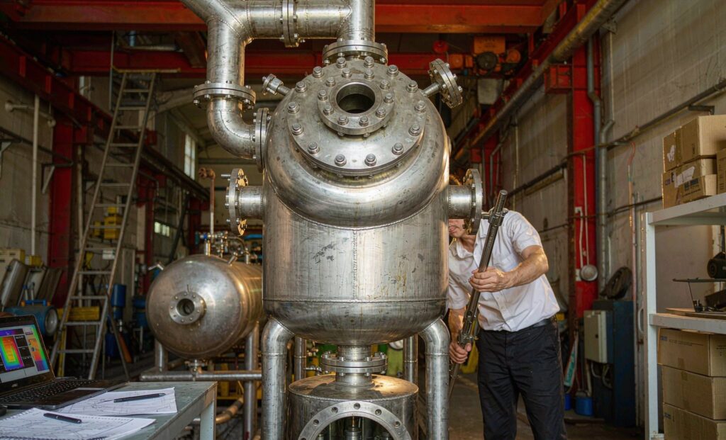
What a heat exchanger sizing calculation needs before it starts
Every heat exchanger sizing calculation rests on the same foundation: how much heat must move, how hard the temperature difference pushes it, and how well the construction conducts it. Get the input data right and the arithmetic is almost secondary; get it wrong and no amount of software will rescue the selection. Before running any numbers, collect:
- Both fluids, their mass flow rates and operating pressures
- Inlet and outlet temperatures on each side — or three of the four values plus the duty
- Fluid properties: specific heat, density, viscosity, thermal conductivity
- Allowable pressure drop on each side (this constrains velocity more than buyers expect)
- Fouling tendency of each stream and the planned cleaning method
- Any physical envelope, nozzle orientation or existing-tie-in constraints
The method below is the standard LMTD (log mean temperature difference) approach used for preliminary design — the same sequence a manufacturer’s thermal engineer follows before detailed software rating takes over.
Step 1: the heat duty calculation
Heat duty is the energy transferred per unit time:
Q = ṁ × cp × ΔT
where Q is duty in kW, ṁ is mass flow in kg/s, cp is specific heat in kJ/kg·K and ΔT is the temperature change of the stream. On a condenser or evaporator one side changes phase, so the duty comes from latent heat (ṁ × hfg) plus any subcooling or superheat terms. In steady operation the hot-side and cold-side duties must balance — if they do not, either the flows or the assumed heat losses are wrong, and it is better to find that on paper than after commissioning.
Worked example: cool 10 kg/s of process water from 70 °C to 40 °C. Q = 10 × 4.18 × (70 − 40) = 1,254 kW. If cooling water enters at 28 °C and leaves at 38 °C, its flow must be 1,254 / (4.18 × 10) = 30 kg/s.
Step 2: the LMTD calculation
Because the temperature difference changes along the exchanger, the driving force is the log mean, not the arithmetic mean:
LMTD = (ΔT₁ − ΔT₂) / ln(ΔT₁ / ΔT₂)
For counter-flow (hot inlet opposite cold outlet — nearly always the preferred arrangement): ΔT₁ = Th,in − Tc,out and ΔT₂ = Th,out − Tc,in. In the example: ΔT₁ = 70 − 38 = 32 K, ΔT₂ = 40 − 28 = 12 K, so LMTD = (32 − 12) / ln(32/12) = 20.4 K. Counter-flow always yields a higher LMTD than parallel flow for the same terminal temperatures, which is why it needs less area — use parallel flow only when the process forces it.
Step 3: choosing the overall heat transfer coefficient
The overall heat transfer coefficient U bundles film coefficients, wall conduction and fouling into one number in W/m²·K. It depends far more on the fluids and velocities than on the brand of exchanger. Typical clean-service ranges for preliminary work:
| Exchanger type and service | Typical U (W/m²·K) |
|---|---|
| Plate heat exchanger — water to water | 3,000–7,000 |
| Shell and tube — water to water | 1,000–2,500 |
| Shell and tube — condensing steam to water | 1,500–4,000 |
| Shell and tube — oil to water | 200–500 |
| Shell and tube — gas to gas | 20–100 |
| Air-cooled exchanger — liquid to air | 30–100 |
Treat any table value as a starting assumption to be verified by rating calculations, not as a design guarantee. Plate units achieve high U values because the corrugated plates promote turbulence at low flow rates; gas and oil services sit orders of magnitude lower because film resistance dominates.
Step 4: the heat transfer surface area
Combine the pieces with the design equation:
A = Q / (U × F × LMTD)
F is the LMTD correction factor — 1.0 for pure counter-flow, roughly 0.75–0.95 for multi-pass shell and tube. Continuing the example with a two-pass shell and tube unit, U = 1,500 W/m²·K and F = 0.88:
A = 1,254,000 / (1,500 × 0.88 × 20.4) ≈ 46.4 m² of heat transfer surface. From there a designer lays out real geometry — tube diameter, length, count and pitch — that delivers at least that area inside the allowable pressure drop. For the same duty a gasketed plate unit would typically need roughly half the area and a fraction of the volume thanks to its higher U.
Step 5: fouling factor and design margin
A unit sized for clean conditions will underperform within months in most services. Fouling resistance is added to the overall resistance:
1/Udesign = 1/Uclean + Rf,hot + Rf,cold
Representative values: treated cooling tower water ≈ 0.00018 m²·K/W, untreated river water ≈ 0.00035, clean steam ≈ 0.00009, heavy oils ≈ 0.0009 or more. The equivalent planning shortcut is 10–15% area margin for clean services and 20–30% for fouling ones. Resist the urge to double it: excess area lowers velocities, and low velocities accelerate exactly the fouling you were protecting against — a self-defeating over-design covered further in our article on heat exchanger fouling causes and prevention.
Common sizing mistakes that show up after commissioning
Field failures rarely come from the LMTD formula itself. They come from the assumptions around it:
- Sizing to average conditions. A unit selected for the annual mean cannot hold process temperature on the hottest afternoon. Size for the design (statistical worst) case, then check that part-load operation — especially turndown in evaporators — stays stable.
- Forgetting heat gains. Pumps, agitators and solar load on outdoor piping add duty that never appears on the process flow diagram. Ten percent unaccounted heat is a ten percent undersized exchanger.
- Ignoring viscosity at the cold end. Oils and syrups thicken dramatically near their pour point; a U-value taken from a table at 80 °C wildly overstates performance at 20 °C.
- Assuming nominal flow. Real circuits deliver whatever the pump curve and pressure drop allow, not the nameplate figure. If the calculation depends on an exact flow, verify it against the pump curve at the calculated system resistance.
- Copying a U-value from a different geometry. A plate exchanger’s U is not transferable to shell and tube duty at equal velocities — the film coefficients belong to the surface geometry.
Plate or shell and tube: how the same calculation lands differently
Run the identical numbers for a plate and a shell and tube unit and the divergence appears immediately. The plate unit’s high U shrinks the required area, so for clean water-to-water duties a plate pack needs roughly half the surface and a fifth of the installed volume, at the cost of a narrower pressure-drop budget and a low fouling tolerance. The shell and tube unit accepts higher pressures and dirtier fluids and offers tube-side mechanical cleaning, which is why it still dominates refineries, gas processing and steam surface condensers. The calculation does not choose for you — it quantifies the trade-off so the choice can be defended. Our shell and tube vs plate heat exchanger comparison works through several real duties on exactly this basis.
What the calculation cannot tell you
The LMTD sizing calculation answers “how much area?”, not “will this unit survive 20 years of duty?” A complete design also checks:
- Pressure drop on both sides against pump and compressor capability
- Flow-induced vibration in shell and tube bundles, especially with compressors upstream
- Material compatibility — chlorides versus stainless, ammonia versus copper, seawater demanding titanium
- Phase-change behavior — dry-out limits in evaporators, condensate drainage, freezing margin
- Maintenance access — which side fouls, and whether the construction allows cleaning it
This is why a serious manufacturer runs the full rating software, not just the hand calculation, before committing steel. Zhenggong Cooling and Heating Equipment Co., Ltd provides complete thermal design as part of its engineering service — D1/D2 pressure vessel certified and ISO 9001/ISO 14001 audited, manufacturing shell and tube, plate and air-cooled equipment for worldwide export since 2016. The global engineering service page describes how a duty sheet becomes a certified drawing package, and our overview of shell and tube heat exchanger construction shows how those design choices materialize in hardware — for example in the stainless shell and tube heat exchanger built for hygienic and corrosive duties.
From calculation to specification
A disciplined hand calculation gets you 80% of the way to a purchasable specification: duty, LMTD, U with fouling, area, and a margin you can defend. The remaining 20% — geometry, vibration, codes and testing — is what a thermal manufacturer adds. If you have a duty to size, send the temperatures, flows and fluid data to Zhenggong’s engineering team and request a rated selection with performance guarantee and export pricing.