
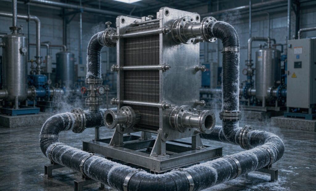
Why an IQF Freezer Needs a Heat Exchanger at All
An IQF freezer heat exchanger sits in the plant room, not in the tunnel, and that is precisely why it gets neglected. The tunnel coil is the visible equipment — the one that frosts up, the one maintenance walks past. The plate or shell-and-tube unit that transfers heat from the glycol loop into the ammonia plant is a box on a skid, and when throughput drops or the tunnel takes longer to pull down after defrost, nobody looks at it first.
In a modern individual quick freezing line, though, that unit sets the whole temperature stack. Every kelvin of approach temperature it costs you has to be paid for by running the ammonia plant colder, which costs compressor power continuously and reduces capacity exactly when you need it. This guide covers the secondary refrigerant loop, the temperature stack that governs its design, the material rule that eliminates most of the exchangers on the market, and the numbers to put in an RFQ.
Why IQF Lines Use a Glycol Loop Between Ammonia and the Tunnel
Ammonia is the most efficient industrial refrigerant available and remains the default for large freezing capacity. It is also toxic, and at concentrations above roughly 300 ppm it is an immediate health hazard. A direct-expansion ammonia coil inside a food production room places high-pressure liquid refrigerant within metres of open product, which is difficult to defend under BRCGS, FSSC 22000 or any export-market audit that a frozen vegetable or fruit processor is likely to face.
The standard answer is a secondary refrigerant. Ammonia is confined to a ventilated, gas-detected plant room; food-grade propylene glycol carries the refrigeration effect into the tunnel. The boundary between the two is a single heat exchanger, and every design decision about that unit follows from the fact that it is also the safety barrier.
What the secondary loop costs you
A secondary loop is not free. It introduces one more heat transfer step, one more pump, and one more fluid to manage. The temperature penalty is the important one: to deliver glycol at −40 °C to a tunnel coil, the ammonia must evaporate several kelvin below that, and at those temperatures ammonia pressure ratios climb steeply. The design consequence is usually two-stage compression or a booster arrangement — a capital decision that was triggered by a few kelvin across a plate pack.
This is the argument for specifying the exchanger properly. A unit with a 1 K approach instead of 3 K may allow a single-stage plant to stay within its pressure ratio limit, or may allow the same compressor to hold a lower tunnel temperature on a hot summer day. That is worth more than the price difference between two plate packs.
The Temperature Stack: Where the Losses Accumulate
Work down from the compressor to the product core and the penalties add up in a predictable sequence. Each row is a design choice someone made, and each one has a cost in compressor power.
| Stage | Typical temperature | What governs it | Cost of getting it wrong |
|---|---|---|---|
| Product core out of tunnel | −18 °C or colder | Customer specification and cold-chain regulation | Rejection, or recrystallisation in storage |
| Tunnel air | −30 to −35 °C | Heat transfer rate needed for the dwell time on the belt | Longer dwell, larger tunnel, or clumping |
| Glycol supply to coil | −35 to −40 °C | Tunnel air temperature plus coil approach | Larger coil, more fan power |
| Glycol return from coil | 3–6 K warmer than supply | Flow rate and coil duty | Higher flow, more pump power, or wider ΔT and colder supply |
| Ammonia evaporating | −40 to −48 °C | Glycol supply minus exchanger approach | Lower suction pressure, worse compressor volumetric efficiency, possible two-stage requirement |
| Ammonia condensing | +35 to +55 °C | Ambient and condenser type | Pressure ratio, and in hot climates the dominant efficiency loss |
Two rows in that table are usually fixed by the product and the climate. The exchanger approach is the one that is still open when the equipment is being bought, and it is the cheapest place to recover a kelvin. A practical target for a glycol–ammonia plate unit is 1.5–2.5 K at design duty, with the pressure drop on the glycol side kept low enough that the secondary pump does not consume the saving.
Establishing the Duty: Heat Load From Throughput
IQF exchangers are frequently ordered against a kW figure inherited from a previous line. It is worth re-deriving it, because the number depends heavily on the product.
For a vegetable or fruit product entering at around +15 °C and leaving at −18 °C, the enthalpy removed is roughly:
- Sensible cooling above freezing: about 3.6 kJ/kg·K over roughly 33 K — around 120 kJ/kg.
- Latent heat of freezing: 250–300 kJ/kg for products at 75–90% water content — the largest single term.
- Sensible cooling below freezing: about 1.9 kJ/kg·K over 18 K — around 35 kJ/kg.
That totals approximately 420–460 kJ/kg, or 115–130 kWh per tonne. A 2 t/h line therefore needs 230–260 kW of refrigeration at the tunnel, before any allowance for fan heat, belt load, infiltration and defrost recovery. A 15–20% margin brings the exchanger duty to roughly 280–310 kW. High-fat or high-sugar products such as diced fruit in syrup sit at the upper end; low-moisture products such as pastry or bread sit far lower, and a unit sized for vegetables will be badly oversized for them.
Two further cases must be stated explicitly in the RFQ, because they change the selection more than the nominal duty does:
- Pull-down after defrost. Hot-gas defrost returns the coil and tunnel to a much higher temperature. The exchanger must handle the recovery load, which can be 1.3–1.5 times steady-state for 10–20 minutes.
- Warm start. A line started with a warm tunnel and warm product demands peak capacity for the first hour. If the exchanger is selected on steady state only, this is when the ammonia plant trips on low suction pressure.
The Material Rule That Eliminates Most Units
Ammonia attacks copper and copper alloys. This single fact rules out the most common and cheapest plate heat exchanger construction — copper-brazed — on any circuit that contains ammonia, and it is the reason IQF secondary loops are not specified like HVAC chilled water loops.
| Construction | Ammonia side | Glycol side | Verdict for IQF duty |
|---|---|---|---|
| Copper-brazed plate | Not acceptable | Acceptable | Only where the unit is entirely on the glycol side and never sees ammonia |
| Semi-welded plate (laser-welded cassette) | Welded, 316L | Gasketed, openable | The usual best fit — pressure-tight on ammonia, cleanable on glycol |
| All-welded or fusion-bonded plate | Welded, 316L | Welded | Good for high pressure and large capacity; not openable for mechanical cleaning |
| Shell and tube, stainless or carbon steel | Compatible | Compatible | Preferred where the glycol side may foul or where very large duty and high pressure coincide |
Note the fourth column carefully. A copper-brazed exchanger is perfectly serviceable on the glycol side of a cascade, for example between the glycol loop and a chiller or a CO₂ circuit. It is only unacceptable where ammonia is present. Suppliers who quote a brazed unit for an ammonia-to-glycol duty have either misunderstood the application or are hoping you have.
On the glycol side, 316L plates are the default. Food-grade propylene glycol rather than ethylene glycol is standard where a leak could reach product — a leak path exists in any gasketed unit, and the consequence of ethylene glycol contamination is a product recall rather than a maintenance ticket.
Glycol Selection: Concentration, Viscosity and the Pump Penalty
The glycol loop is where IQF systems most often disappoint in service, and the reason is viscosity. Propylene glycol at −40 °C is not the thin fluid it is at room temperature; its viscosity rises by two orders of magnitude, and pump power and pressure drop rise with it.
Concentration has to be set from the freeze point with a margin, not from a rule of thumb. Roughly 40% propylene glycol by volume protects to about −20 °C; 50% to roughly −33 °C; 55–60% is needed for a −40 °C supply with any margin. Running a 45% mix because that is what was on site is a common cause of slush formation at the coil during a cold pull-down, which shows up as erratic tunnel temperature and unexplained capacity loss.
The design consequences are concrete:
- Size channels for the cold viscosity, not for water. A plate pack selected on water properties will show a pressure drop three to five times the calculated value once the loop is at temperature.
- Keep glycol velocity high enough for heat transfer but accept a wider channel. Deep channels cost surface area but pay for themselves in pump power at −40 °C.
- Specify the pump on the cold condition. Pumps selected on warm commissioning data are routinely undersized.
- Account for the higher specific heat demand. Propylene glycol at 50% has a specific heat around 3.3 kJ/kg·K against water’s 4.18, so the flow rate for the same duty is roughly 25% higher than a water-based calculation suggests.
Glycol also degrades. Inhibitor packages deplete, pH falls, and the fluid turns acidic. At the low temperatures in an IQF loop the degradation is slower than in a solar loop, but it is not zero, and the resulting sludge goes straight into the narrowest passages in the system. Annual testing of pH, reserve alkalinity, concentration and appearance is the minimum, with replacement on the fluid supplier’s schedule.
A Step Checklist for Specifying the Unit
An RFQ built on these ten points will produce comparable quotations and a unit that behaves as expected in service.
- State both circuits — refrigerant and secondary fluid — with concentrations, not just “glycol”.
- Give four temperatures for each circuit at design duty, and separately at warm start and post-defrost recovery.
- Give the freezing duty in kW and the product throughput, moisture and inlet temperature it was derived from.
- State the maximum approach temperature as a hard requirement, with the ammonia evaporating temperature it implies.
- Give allowable pressure drop on both sides at the cold viscosity, not at 20 °C.
- Specify construction: semi-welded, all-welded or shell and tube, with the ammonia side welded.
- Specify materials for plates, gaskets, nozzles and frame, including gasket compatibility with propylene glycol.
- State the design pressure and temperature for both sides, and the code the unit must be built and stamped to.
- Ask for the pressure vessel certification the project will require at handover. Zhenggong manufactures to D1 and D2 pressure vessel certification and operates under ISO 9001 and ISO 14001, which covers the documentation typically requested for food plant installations.
- Ask how the unit is cleaned — chemically in place, or opened — and what clearance that needs in the plant room.
Installation Details That Decide Whether It Works
Three installation points cause most of the service calls on IQF secondary exchangers, and none of them is the exchanger’s fault.
Air in the glycol loop. A loop that is not properly vented at its high points will trap air, and air in a plate pack produces a pressure drop that rises and falls with pump speed while the outlet temperature wanders. Fill slowly, vent at the highest point and at the exchanger, and fit an automatic air vent at the top of the primary header.
Strainers and debris. Construction debris in a plate channel cannot be removed without opening the pack. Fit a strainer upstream of the exchanger on both circuits and clean it after the first week, then monthly for the first quarter.
Defrost water and ice. Where the exchanger is installed near the tunnel rather than in a separate plant room, defrost water and condensate must be drained away from it. Ice forming on a frame or a nozzle is a slow route to a cracked weld.
Getting the Temperature Stack Right
The IQF freezer heat exchanger is a small line item that governs compressor selection, tunnel dwell time and energy consumption for the life of the line. It is worth specifying on approach temperature and cold-condition pressure drop, not on price per kilowatt.
If you are building or upgrading a freezing line, send us the product, the throughput, the tunnel air temperature and your ammonia condensing condition. We will return a selection with the approach temperature stated, the implied evaporating temperature, and the pressure drop at operating viscosity. The product range covers both routes: the stainless shell and tube heat exchanger for large ammonia duties and dirty glycol, and welded plate construction where the plant room is tight.
For the refrigeration side of the calculation, our guide to air cooled condenser sizing for cold storage covers the condensing end of the same cycle, and the ammonia refrigeration heat exchanger guide covers plates versus shell and tube on R717 duty. Application notes by industry are indexed on the applications page.
Send your duty through the contact page and include the post-defrost recovery case — it is the one that most often changes the answer.