
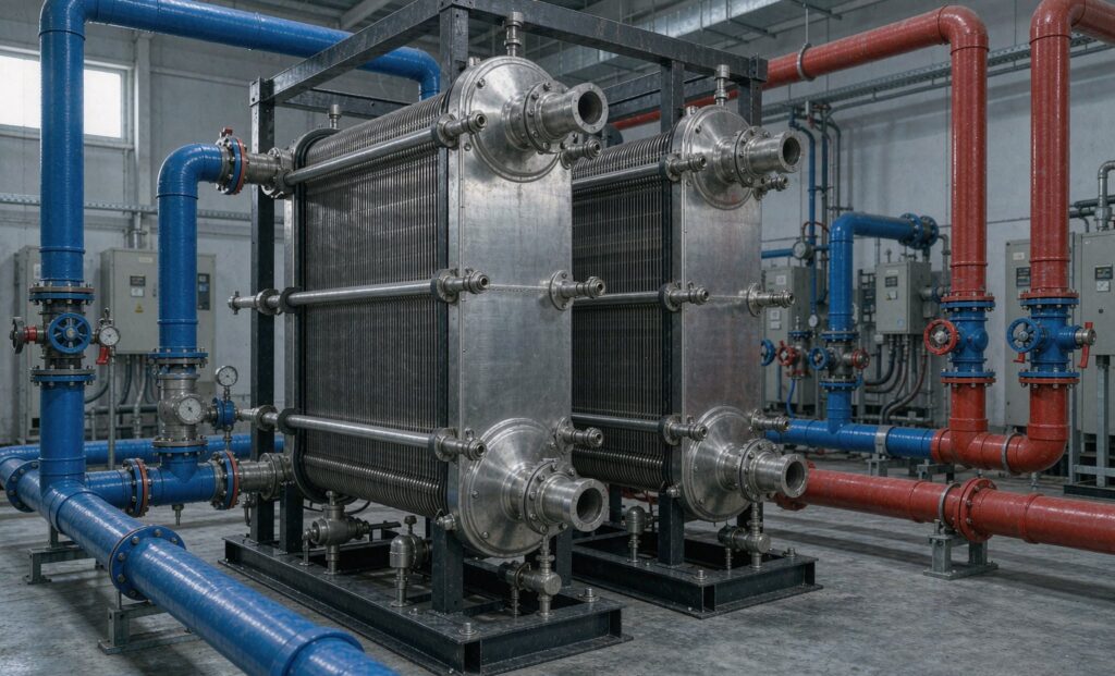
Where the Heat Exchanger Sits in a Ground Source Heat Pump System
A geothermal heat pump heat exchanger has one job that is easy to state and hard to do well: transfer heat between a buried ground loop and the building side of the system without letting the two fluids mix, without eating the pump head, and without losing capacity as the approach temperature closes. On small residential systems the loop connects straight to the heat pump and no separate exchanger exists. Above roughly 50 kW of connected load — and on almost every commercial or district scheme — a plate or shell and tube unit is inserted between the ground loop and the machine, and its selection decides how much of the ground’s capacity you actually get to use.
The reason is separation of circuits. The ground loop carries a glycol or brine mixture at a concentration set by the local frost depth, picks up silt and biological growth from the ground, and is often installed by a different contractor than the plant room. The building side carries treated water through the heat pump, buffer tanks and distribution. An intermediate exchanger keeps the two apart, allows each circuit to run at its own pressure and its own expansion vessel, and gives maintenance a single isolation point. It also introduces a temperature penalty: every exchanger has an approach, and in a geothermal system that approach is paid for directly in compressor lift.
That trade — decoupling versus approach loss — is the whole design problem. The rest of this guide works through it with the numbers that matter.
Start With the Ground Loop Fluid, Not the Load
Glycol concentration is normally chosen by the coldest ground loop temperature with a safety margin, not by the heat pump. A 30% propylene glycol mix protects to about −13 °C; 40% to about −22 °C. Both figures carry a penalty, and the penalty is larger than most designers assume when they size the exchanger after the fact.
| Propylene glycol concentration | Freeze protection | Specific heat vs water | Viscosity at 0 °C vs water | Effect on loop flow |
|---|---|---|---|---|
| 0% (water only) | 0 °C | 4.19 kJ/kg·K | 1.0× | Baseline |
| 20% | −8 °C | 4.02 kJ/kg·K (−4%) | ≈1.6× | +4% flow for the same duty |
| 30% | −13 °C | 3.90 kJ/kg·K (−7%) | ≈2.2× | +8% flow, noticeably higher ΔP |
| 40% | −22 °C | 3.75 kJ/kg·K (−11%) | ≈3.0× | +12% flow, and the plate may need wider channels |
| 50% | −33 °C | 3.60 kJ/kg·K (−14%) | ≈4.2× | Channel selection and pump sizing both change |
Two consequences follow. First, the exchanger must be selected on the glycol side’s actual viscosity at the lowest expected loop temperature, not at 20 °C. A plate selected at ambient viscosity can show double the pressure drop in February. Second, in a plate exchanger the channel geometry has to be chosen for the brine, not the water side — wide-gap or free-flow channels where the loop fluid is silty, standard herringbone where it is clean. This is where a catalogue selection and a proper thermal design diverge.
Approach Temperature Is the Whole Economic Argument
Approach, or terminal temperature difference, is the gap between the ground loop leaving temperature and the building loop entering temperature at one end of the exchanger. A 1 K approach is achievable with a large plate pack; 2 K is the usual commercial target; 3 K costs less and is common on retrofit work.
In a geothermal heat pump each extra kelvin of approach raises the condensing temperature (in heating) or lowers the evaporating temperature (in cooling) by the same amount, and the compressor pays for it. As a working figure, a water-to-water heat pump loses 2–3% of COP per kelvin of increased lift. On a 300 kW heating duty running 2,000 equivalent full-load hours, moving from 1 K to 3 K approach is worth roughly 12–18 MWh of electricity a year — usually several times the price difference between the two exchanger sizes.
So the approach temperature belongs in the specification as a hard requirement with a stated duty point, not as an outcome. State it as: ground loop 4 °C in / 1 °C out, building loop 1.5 °C in / 4.5 °C out, approach 1.5 K at both ends, duty 300 kW. A supplier can then be held to it.
Plate or Shell and Tube: Choosing the Geothermal Heat Pump Heat Exchanger Type
Both are used, and the correct answer depends on water quality and load size more than on anything else.
| Criterion | Gasketed plate | Shell and tube |
|---|---|---|
| Overall heat transfer coefficient | 3,000–6,000 W/m²·K | 800–2,000 W/m²·K |
| Approach achievable | 0.5–1.5 K | 2–5 K |
| Footprint for the same duty | Smallest — often one quarter | Largest |
| Suspended solids tolerance | Poor; channels 2–4 mm, blocks on silt | Good; tube bores 15–25 mm |
| Flow per unit | Typically 10–150 m³/h | Up to 500 m³/h and beyond |
| Cleaning | Dismantle and wash plates in place | Chemical clean, or bundle withdrawal on removable types |
| Pressure limit | 0.6–1.6 MPa standard, 2.5 MPa on reinforced frames | 1.0–2.5 MPa routine, higher on request |
| Gasket life | 2–5 years in brine service, and a recurring cost | No gaskets in the heat transfer path |
The practical rule that emerges from installed systems: a closed vertical borehole loop with clean, properly flushed brine is plate territory, and a plate exchanger will deliver a 1 K approach in a plant room corner. An open loop drawing groundwater, a surface-water loop, or any circuit where the installer cannot guarantee a flushed and filtered fluid is shell and tube territory. A plate exchanger on a silty open loop will block within one heating season, and the resulting outage costs far more than the efficiency gain was worth.
Where the loop fluid is aggressive — high chloride groundwater, brackish surface water, seawater-adjacent sites — the plate material question becomes the binding constraint. Our comparison of titanium versus cupronickel for seawater cooling sets out where 316L stops and titanium becomes mandatory.
Materials: Where 316L Stops Being Enough
Brine circuits are usually benign for stainless. Propylene glycol itself is not corrosive to 316L, and a closed, deaerated loop with correct inhibitor levels will run for decades. The failure modes that matter are different from what most specifications anticipate.
- Chlorides. 316L is generally limited to about 200 mg/L chloride at ambient temperature, falling as temperature rises. Above that, pitting and crevice corrosion start at the gaskets, which is exactly where you cannot see them.
- Dissolved oxygen from poor commissioning. A loop left with air in it, or topped up repeatedly with raw water, corrodes stainless far faster than the chloride figure alone suggests.
- Galvanic coupling. Stainless plates in a carbon steel frame with brass connections need insulating washers or the frame becomes the anode.
- Biological fouling. Iron bacteria and sulphate reducers in groundwater loops produce deposits that look like scale and behave like an insulating blanket.
Material recommendation for the common cases: 316L plates for closed borehole loops; titanium plates for open loops with chloride above 200 mg/L or any seawater influence; carbon steel shell with 316L or titanium tubes for large shell and tube units. Gaskets in brine service are usually NBR for temperatures below 90 °C; EPDM where free chlorine or ozone cleaning is used.
Pressure Drop Is a Hidden Cost in Every Geothermal Loop
The circulation pump on a ground loop runs continuously through the heating and cooling season — often 4,000 to 6,000 hours a year. Every 10 kPa of additional exchanger pressure drop is pumped 5,000 times over, and unlike the compressor penalty it is easy to overlook because it appears in a different line of the energy model.
Set a budget before selecting: 20–30 kPa on the ground loop side and 20–30 kPa on the building side is a reasonable target for a commercial scheme. If a proposed unit needs 60 kPa to hit the approach, either accept a slightly wider approach or accept a larger plate pack — do not simply buy the higher pressure drop and let the pump absorb it. On geothermal systems the pump energy is a meaningful fraction of total system energy, and it is the part most often left out of the payback calculation.
Commissioning Details That Decide Whether the Rating Is Ever Reached
Most geothermal exchanger complaints are installation faults, not selection faults. The sequence below is worth enforcing on site.
- Flush the ground loop before connecting the exchanger. Construction debris, drilling mud and pipe swarf must be out of the loop before it reaches a plate pack. Flush to a temporary bypass with a strainer in line until the strainer stays clean.
- Fit a strainer upstream of the exchanger on the ground loop side, with a mesh sized to the narrowest channel — typically 0.8–1.0 mm for a standard plate.
- Verify glycol concentration by refractometer after filling, and record it. A pre-mixed drum is not a guarantee of what is in the loop.
- Vent both sides properly. Trapped air in a plate exchanger produces a high-pressure-drop, low-duty condition that reads exactly like fouling.
- Record the baseline pressure drop and temperatures at design flow on the commissioning sheet. Without that number, no future maintenance decision has a reference point.
- Insulate both circuits and the exchanger where condensation is possible — a cold brine line in a humid plant room will drip continuously.
- Check the expansion vessel sizing on both circuits independently. A shared vessel is a common and expensive shortcut.
Maintenance Calendar for a Ground Loop Exchanger
- Monthly: log pressure drop and approach temperature at a known flow. Trend, do not react to single readings.
- Quarterly: check glycol concentration and pH; top up with pre-mixed fluid only, never neat glycol and water separately.
- Annually: clean the strainer, inspect for weeping at gaskets, and confirm the control valves are not hunting.
- Every 3–5 years: dismantle a plate unit, inspect gaskets for hardening and compression set, and re-torque to the manufacturer’s dimension rather than a torque figure.
- On any capacity complaint: verify flow first, then approach, then fluid condition. Only then open the exchanger.
For the building-side counterpart to this equipment — chilled water plants, buffer separation, and the terminal side of the same systems — our guide to chilled water plate heat exchangers in HVAC plants covers the selection sequence in the same terms.
Specifying the Unit: What to Send
A geothermal enquiry needs a small, specific dataset. Suppliers who receive it can guarantee an approach; those who do not will quote a surface area and disclaim the performance.
- Duty in kW, separately for heating and cooling if the system reverses.
- Ground loop fluid: glycol type and percentage, or brine composition, with the minimum loop temperature.
- Four temperatures and two flow rates, plus whether flow is constant or variable.
- Required approach at each end, at the stated duty.
- Allowable pressure drop per side at design flow.
- Design pressure on both sides, and whether the circuits must be able to be isolated independently.
- Water quality analysis for open loops — chloride, iron, suspended solids, hardness.
- Installation constraints: available footprint, connection orientation, indoor/outdoor, ambient temperature.
Zhenggong manufactures gasketed and brazed plate exchangers and shell and tube units for ground source, water source and air source heat pump systems at its 35,000 m² facility in Shandong, under D1/D2 pressure vessel certification and ISO 9001 and ISO 14001. See the brazed and fusion bonded plate heat exchanger range for heat pump duties, or the complete product range for the tubular alternative. To have a selection run against your loop conditions, send the eight data points above to the engineering team and you will receive a thermal design with the approach and pressure drop guaranteed in writing.