
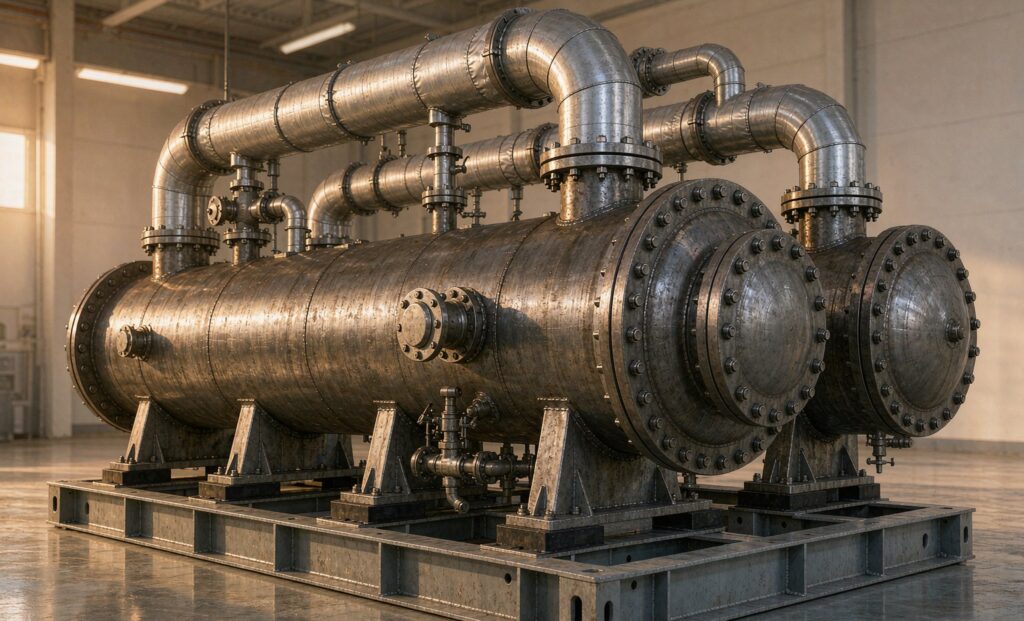
Why a Thermal Oil Heat Exchanger Is Not a Steam Heater With a Different Fluid
Most thermal oil heat exchanger problems trace back to one design habit: treating hot oil as if it were steam. It is not. Steam delivers heat as latent energy at a fixed temperature; thermal oil delivers it as sensible heat, which means the oil cools as it gives up energy and its viscosity rises with every degree it drops. A unit selected on the same assumptions used for a steam bundle will usually be undersized on the oil side, oversized on pressure drop, and short-lived at the tube wall.
Thermal oil loops are chosen for a reason. They reach 250–320 °C at near-atmospheric pressure, where saturated steam would need 40–120 bar. That combination — high temperature, low pressure, no phase change — is why hot oil circuits dominate asphalt plants, textile stenters, plywood and MDF presses, chemical reactors, bitumen storage, and heat transfer in food frying lines. It is also why the exchanger at the centre of the loop has to be specified on different terms from anything on a steam header.
This guide covers the numbers that actually govern selection, the shell-and-tube versus plate decision, the failure mode that destroys more hot oil systems than corrosion does, and the checks that belong in a specification before a purchase order is raised. The same logic applies whether you are building a new loop or replacing a bundle that never met its duty.
The Three Numbers That Decide the Design
Before a supplier can quote a thermal oil heat exchanger honestly, three figures must be fixed. Everything else — surface area, shell diameter, baffle spacing, material — follows from them.
| Input | Typical range | Why it governs the design |
|---|---|---|
| Oil supply and return temperature | 180–320 °C supply, 20–40 °C drop across the loop | Sets the LMTD and, critically, the oil viscosity at the coldest point of the exchanger |
| Oil flow rate | Set by heater rating, not by the exchanger | Determines tube-side velocity; low flow is the single most common cause of coking |
| Process fluid in and out | Often 20–200 °C | Fixes the approach temperature and whether a single pass can achieve it |
| Maximum allowable pressure drop | 0.3–0.8 bar on the oil side is typical | Directly trades against velocity; the two cannot both be maximised |
| Fluid maximum film temperature | Typically 20–40 °C above bulk maximum | A hard limit, not a guideline — exceed it and the oil cracks |
The trap is the second and fourth rows together. A pump curve and a pipe size will happily deliver a flow rate that gives 0.9 m/s through a 25 mm tube — adequate for water, marginal for oil at 250 °C. Drop to 0.4 m/s and the oil film at the wall sits far hotter than the bulk temperature. That film is where thermal cracking begins.
Film Temperature: The Failure Mode That Ends Most Hot Oil Systems
Organic heat transfer fluids degrade by thermal cracking, and cracking is a function of film temperature and time, not of bulk temperature. The heater is usually blamed, but the exchanger contributes just as much. A fouled oil-side surface, a low-velocity dead zone behind a baffle, or a hot-oil inlet impinging directly on a tube sheet all create local metal temperatures well above the loop setpoint.
Once cracking starts, the sequence is predictable:
- Carbon deposits form on the oil-side surface. The deposit is an insulator, so the metal runs hotter still to move the same heat — a self-accelerating loop.
- Pressure drop rises while outlet temperature falls. Operators compensate by raising the supply setpoint, which accelerates the next round of cracking.
- Acid number and viscosity drift. A fluid analysis shows the trend long before the plant notices a capacity loss.
- Sludge migrates to low points and narrow passages — control valves, orifice plates, and in a plate exchanger the plate channels, which block first.
Three design measures keep film temperature under control. First, keep oil velocity above roughly 1 m/s at the operating viscosity, which usually means more passes or a smaller tube diameter rather than a bigger shell. Second, avoid a direct high-velocity impingement on the tube sheet at the oil inlet — an impingement plate or an enlarged inlet nozzle is cheap at the drawing stage. Third, do not specify a design fouling factor so conservative that it forces the surface area up and the velocity down; on hot oil service that trade is usually wrong. Fluid analysis at 6-month intervals, tracking acid number, viscosity and insolubles, is the cheapest instrumentation on the loop.
Shell and Tube or Plate for Hot Oil Duty
Both configurations are sold into hot oil service, and both can work. The choice turns on temperature, gasket material, and how clean the oil circuit actually stays in practice.
| Criterion | Shell and tube | Gasketed plate |
|---|---|---|
| Upper temperature | No practical limit with carbon steel and graphitic gaskets | Gasket-limited; above roughly 180 °C the elastomer options narrow sharply |
| Fouling and coking tolerance | Good — large shell-side passages, mechanical cleaning possible | Poor — 2–4 mm channels block permanently if sludge forms |
| Thermal expansion at 250 °C+ | Handled by U-tube, floating head or an expansion bellows on fixed tube sheet | Handled by the plate pack; not a constraint |
| Footprint per kW | Larger | Roughly one third to one fifth |
| Oil inventory | Higher — a real cost at synthetic fluid prices | Low |
| Cleaning | Bundle withdrawal or chemical circulation | Full dismantle in place |
| Best fit | Above 200 °C, high ΔT, dirty or unknown oil condition | Clean synthetic oil, moderate temperature, tight plant room |
In practice, a thermal oil heat exchanger above 250 °C is almost always a shell and tube unit. Below 180 °C, with a well-maintained synthetic fluid and a filter in the loop, a gasketed plate exchanger is compact and efficient and should be considered seriously. Between those two figures the decision is economic and depends on gasket availability, oil cleanliness history, and whether the plant has the space.
A fixed tube sheet design at 300 °C oil inlet and 30 °C process inlet will see enough differential expansion to require an expansion bellows or a U-tube bundle. This is not a detail to leave to the fabricator. If the datasheet does not state which construction is offered, ask — a fixed tube sheet without a bellows on that duty will crack at the tube-to-tube-sheet joint within a few thermal cycles.
For readers weighing the wider tubular configuration question, our guide to shell and tube heat exchangers for steam service covers TEMA rear-end types and where each one fails. The same rear-end logic applies here, with the added constraint of a fluid that degrades.
Materials and Gaskets for 200–320 °C
Carbon steel is the default for both shell and tubes in a closed, dry, nitrogen-blanketed hot oil loop. Stainless is often specified for the wrong reason — high temperature alone does not require 316L. What does require it is a wet loop, a corrosive site atmosphere, or a fluid that has degraded to the point of producing acids.
- Shell and channel: ASTM A516 Gr.70 or equivalent for most duties; 304/316L where the oil is acidic or the loop cannot be kept dry.
- Tubes: seamless carbon steel 10 or 20 gauge; stainless where velocity or fluid condition demands it. Thin walls raise the oil-side film coefficient but leave less corrosion allowance.
- Gaskets: spiral-wound with graphite filler and 316 inner ring is the standard choice at 300 °C. PTFE is not suitable above roughly 200 °C in this service; EPDM and NBR are out of their range entirely.
- Insulation: rock wool or calcium silicate with a proper vapour barrier. Uninsulated hot oil flanges are both a burn hazard and a heat loss that shows up as a shortfall in process temperature.
Where the unit falls under a pressure equipment directive or a national code, the design registration matters as much as the material certificate. Zhenggong holds D1 and D2 pressure vessel certification plus ISO 9001 and ISO 14001, which covers the class of vessel a typical hot oil exchanger requires; confirm that the class on offer matches your jurisdiction before ordering.
Specification Checklist
Send all of the following with an enquiry. A supplier who receives a complete package can quote a guaranteed duty; one who receives half of it will quote a size and leave the risk with you.
- Fluid name, manufacturer and grade on both sides, with the fluid datasheet attached.
- Mass or volumetric flow on both sides, and whether it is fixed or turndown.
- Inlet and outlet temperatures on both sides — all four, not just the duty.
- Design pressure and design temperature for both sides, stated separately from operating values.
- Maximum allowable pressure drop on each side, at design flow.
- Fouling factors, or an instruction to use the supplier’s standard values with the basis stated.
- Corrosion allowance and any material restrictions.
- Connection sizes and facing standard, plus nozzle orientation if the plant layout is fixed.
- Installation: horizontal or vertical, indoor or outdoor, ambient conditions, seismic or wind load if relevant.
- Code and certification requirements, including third-party inspection and documentation language.
Maintenance That Actually Prevents Failures
Hot oil systems fail slowly and then all at once. A short annual routine catches most of it:
- Sample the oil twice a year for viscosity at 40 °C, acid number, water content and insolubles. Trend, do not just pass or fail.
- Log oil-side pressure drop at a fixed flow. A 15% rise over baseline is the earliest reliable indicator of coking or sludge.
- Check the vent and expansion tank. Low level means the loop is losing fluid, usually through a leaking flange or a cracked tube.
- Inspect the tube sheet face at every shutdown for oil weeping at the rolled joints — the first sign of thermal fatigue.
- Verify the bypass and control valve response. A hunting control valve produces cyclic thermal stress on the exchanger that no material selection fully absorbs.
If pressure drop has already climbed and outlet temperature is short, the question becomes clean or replace. Our break-even method for heat exchanger cleaning versus replacement sets out the payback arithmetic for that decision.
Getting the Selection Right the First Time
A thermal oil heat exchanger is a modest line item in a loop that may cost a hundred times more, but it is the component that decides whether the loop holds temperature for fifteen years or loses capacity in three. Select on viscosity at the coldest point, hold the oil velocity up, keep film temperature under the fluid limit, and put the expansion case in writing.
Zhenggong builds shell and tube and plate exchangers for hot oil, steam, water and process duty at its 35,000 m² facility in Shandong, and exports to plants across Europe, the Middle East, Southeast Asia and the Americas. Browse the full product range or the stainless shell and tube heat exchanger page for construction details, then send the ten data points above for a thermal design and quotation. Typical turnaround on a technical proposal is two working days.