
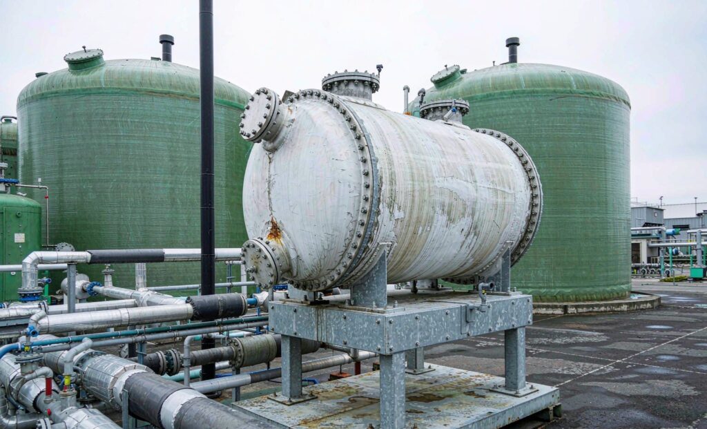
Why Digester Heating Is the Most Under-Engineered Duty in a Biogas Plant
Anaerobic digestion converts organic waste into methane, and the bacteria that do the work are far more sensitive to temperature than most plant designers assume. A mesophilic digester must be held at 35–40 °C continuously; a thermophilic digester at 50–55 °C. Methane yield falls measurably when the digester drifts even two or three degrees below setpoint, and a sustained drop of 5 °C can suppress gas production for weeks while the population recovers.
The equipment responsible for holding that temperature is the biogas digester heating heat exchanger — and it is routinely specified by taking the heat duty from a spreadsheet and picking the cheapest plate unit that fits the number. That approach works on paper and fails in service, because digestate is not water. It is a viscous, fibrous, abrasive, scale-forming slurry that behaves nothing like the fluid in the thermal calculation.
This guide covers how to specify a digester heating heat exchanger that still transfers its rated duty after a year of service, covering duty calculation, exchanger type selection, fouling and struvite control, and the winter load case that catches most designers out.
Calculating the Digester Heat Duty
Digester heating has two separate components, and both must be calculated:
1. Feedstock heating
The energy required to raise incoming feedstock from its delivery temperature to digester temperature:
Qfeed = ṁ × cp × (Tdigester − Tfeedstock)
For digestate, cp is approximately 4.0 kJ/kg·K at 5–8% dry solids, falling toward 3.7 kJ/kg·K at higher solids concentrations. Using the specific heat of water (4.18) systematically overstates the duty, which is a conservative error — but the more dangerous mistake is using summer feedstock temperature as the design case.
2. Structural heat loss
Heat lost through the digester walls, roof and any exposed pipework to ambient. For a well-insulated concrete tank this is typically 10–25 W/m²·K of surface, giving a loss that scales directly with the temperature difference to ambient — and therefore roughly triples between a 15 °C summer and a −5 °C winter.
Add pasteurisation if required
Where the digestate must meet a pathogen-reduction standard — the UK PAS 110 regime, for example, requires 70 °C for one hour — that heat duty is often larger than the digester heating duty itself and must be added to the total. Regenerative pasteurisation, where outgoing hot digestate preheats incoming cold material through a fusion-bonded or brazed plate heat exchanger, can recover 60–80% of that energy and should be evaluated at design stage.
The Winter Case Is the Real Design Condition
This is where most digester heating systems fail. A heat exchanger sized around annual average feedstock temperature and average ambient conditions will meet its duty for eight or nine months of the year and fall short in January — precisely when the digester is most vulnerable to a temperature drop.
The design case must use:
- The lowest credible feedstock temperature — for a plant taking food waste in winter, that can be 5 °C or lower, not the 15–20 °C seen in summer
- The lowest credible ambient temperature for structural losses
- A CHP availability assumption that reflects reality. If the main heat source is the CHP engine’s jacket water, the design must account for engine downtime for maintenance. A backup boiler is usually still required even where CHP heat is nominally ample.
Sizing to the winter case and accepting a slightly oversized exchanger for the rest of the year is the correct trade. Oversizing costs a modest capex premium; undersizing costs gas yield.
Exchanger Type Selection for Digestate Service
Four configurations are used in practice on digester heating circuits. The choice is driven far more by fouling behaviour and cleanability than by thermal performance.
| Type | Typical U-value (W/m²K) | Fouling tolerance | Cleanability | Best fit |
|---|---|---|---|---|
| Gasketed plate | 3,000–5,000 | Low — narrow channels block on fibrous feed | Excellent — can be opened and plate-cleaned | Clean, low-solids digestate; slurry-to-water service with wide plate spacing |
| Brazed / fusion-bonded plate | 4,000–6,000 | Very low — no mechanical cleaning possible | Poor — chemical CIP only | Clean hot-water circuits and pasteurisation regeneration, not raw slurry |
| Shell and tube (fixed tubesheet) | 500–1,200 | Moderate | Fair — chemical cleaning, limited mechanical access | Cleaner process streams; high pressure or temperature |
| Shell and tube (removable bundle) | 500–1,200 | Good — straight tubes pass fibres | Very good — bundle withdrawn for mechanical cleaning | Raw slurry and digestate; the default for high-solids duty |
| Wide-gap / spiral | 400–900 | Excellent — designed for solids and fibre | Good — single-channel spiral is self-scouring | Thick, fibrous, high-solids slurry; the safest choice at 8%+ DS |
The governing principle: a compact exchanger with excellent clean-fluid performance is worthless if operators must dismantle it every three weeks. A larger, lower-U exchanger with generous passages and real cleaning access will deliver more useful heat over a working life measured in years.
Flow velocity matters as much as channel geometry. Too low a velocity lets solids settle and creates stagnant boundary layers that insulate the surface. Too high a velocity increases pressure drop, pumping energy and abrasive wear. The optimum keeps the digestate turbulent enough to limit deposition without excessive pump power — and the supplier should provide pressure drop calculations using representative fluid properties, not water values. A seemingly minor change in solids concentration materially alters both viscosity and pumping behaviour.
Flow Arrangement: Counter-Current Where Recovery Matters
In a parallel-flow exchanger the hot and cold streams enter at the same end and their temperatures converge, limiting how much heat can be recovered. In a counter-current arrangement the streams travel in opposite directions, giving a larger average temperature driving force and allowing the cold outlet to approach the hot inlet much more closely.
For digester heating where the goal is to extract maximum heat from CHP jacket water, counter-current is almost always correct. The exception is where the cold-side outlet temperature must be capped to avoid thermal shock to the biological process — a genuine concern on thermophilic systems, where the return temperature to the digester should be controlled rather than maximised.
Fouling, Struvite and Biofilm: The Dominant Failure Mode
Slurry-side fouling can reduce the U-value by 30–50% within three to six months. Three mechanisms dominate:
- Struvite scaling. Magnesium ammonium phosphate precipitates on hot surfaces where ammonia, magnesium and phosphate coexist — common in digestate from food waste and sewage sludge. Struvite is hard, adherent, and forms preferentially on the hottest surface in the circuit, which is the exchanger’s hot inlet region. Once established, it can only be removed chemically or mechanically.
- Biofilm. A microbial layer that grows on any wetted surface in the 30–45 °C band. It is soft and easier to remove than struvite, but it is continuous and regrows rapidly after cleaning.
- Fibrous and particulate blockage. Undigested fibres, straw, plastics and grit accumulate in narrow passages, progressively reducing flow area and raising pressure drop until the duty collapses entirely.
Countermeasures that work in practice:
- Cap the hot-side surface temperature. Keeping the hottest surface below roughly 55 °C substantially reduces struvite precipitation. This is done by limiting the heating water supply temperature and by keeping the exchanger in a recirculation loop rather than in direct single-pass duty.
- Design around the largest credible solids. Establish the actual maximum particle size and fibre length in the feed before selecting channel width, not after.
- Apply a realistic fouling allowance. An optimistic allowance yields an exchanger that meets specification when clean and fails after three months in service. For slurry duty, a fouling factor equivalent to 20–30% surface area margin is normal.
- Provide real cleaning access. A removable bundle or an openable plate pack, with the isolation valves and drains needed to work on it safely without stopping the digester.
- Instrument the duty. Continuous monitoring of inlet and outlet temperatures on both sides, with an alarm on the temperature approach, detects fouling while there is still time to clean during a planned window.
The broader diagnostics are covered in our guide to heat exchanger fouling causes and warning signs, and where a plant is choosing between refurbishment and replacement, the cleaning vs replacement break-even analysis gives the number-based decision.
Materials of Construction
Digestate is mildly acidic, carries hydrogen sulphide in the gas space, and contains chlorides. Material selection has to account for all three.
- Stainless steel 316L is the baseline for plate packs and the standard choice for digestate service where chloride levels are moderate.
- Duplex stainless steel offers higher strength and better chloride stress-corrosion resistance, allowing thinner plates and higher design pressures. Worth the premium where the feed is saline or chloride content is high.
- Titanium is generally unnecessary for digestate and is a poor choice where hydrogen sulphide is present in the gas phase.
- Carbon steel shells with stainless tubes and tubesheets are a common cost-effective compromise for shell-and-tube units, provided the shell side is the clean hot-water circuit.
- Gasket and seal material must be compatible with both the digestate and any CIP chemicals. EPDM is widely used for digestate where temperature permits; FKM gives higher temperature tolerance at a cost premium.
Integration: CHP Heat, Recirculation and the Backup Boiler
Most digester heating systems take heat from the CHP engine. Recovering heat from the engine’s water circuits creates a useful boundary: the manufacturer’s clean water circuit stays clean, while the dirty digestate passes through equipment designed for sludge. That separation is worth preserving deliberately — do not allow engine jacket water and digestate to share a circuit.
The typical arrangement is:
- CHP jacket water (85–90 °C) transfers heat to a clean secondary heating loop through a shell-and-tube or plate exchanger
- The secondary loop feeds the digester heating exchanger — either an external exchanger with a pumped recirculation loop drawing digestate from the tank, or an internal heating coil in the digester
- A thermostatic control valve modulates the secondary loop flow to hold the digester at setpoint without overheating the biological process
- A backup boiler sits on the secondary loop for CHP downtime and winter peak
External exchangers with a pumped recirculation loop are generally preferred over internal coils: they are accessible for cleaning without entering the digester, and they can be isolated and maintained without taking the digester out of service. For a full treatment of the same selection logic on a different fouling-critical duty, see our shell and tube heat exchanger for steam sizing guide.
Specification Checklist
- Digester type and setpoint temperature, with the acceptable control band
- Feedstock flow rate, dry solids content, and its winter minimum temperature
- Specific heat capacity of the feedstock at the actual solids concentration
- Digester tank dimensions, insulation and calculated structural heat loss at winter ambient
- Pasteurisation requirement, if any, with hold temperature and duration
- Total duty at the winter design case, in kW
- Heat source: CHP jacket water temperature and available flow, plus backup boiler capacity
- Maximum particle size and fibre length in the feed
- Chloride content, pH and ammonia concentration of the digestate
- Exchanger type, with channel or tube geometry justified against the solids data
- Fouling allowance applied and the resulting surface area margin
- Maximum permissible slurry-side pressure drop
- Materials for plates or tubes, shell, tubesheet and gaskets
- Cleaning method and the access required for it
- Instrumentation: temperature transmitters, approach alarm, flow indication
- Isolation valves and drains for maintenance without a digester shutdown
The thermal calculation is rarely the hard part of digester heating. The hard part is transferring heat reliably through a fluid that is thick, fibrous, abrasive and prone to scaling — month after month, through the winter, without stopping the process.
Zhenggong Cooling and Heating Equipment manufactures custom shell and tube, plate, and wide-gap heat exchangers from its 35,000 m² facility in Shandong, China, with D1/D2 pressure vessel certification and ISO 9001 plus ISO 14001 systems, exporting to biogas and waste-to-energy projects worldwide. Send the duty, the solids data and the winter conditions to request a digester heating exchanger selection, and review the wider range on the product range page.