
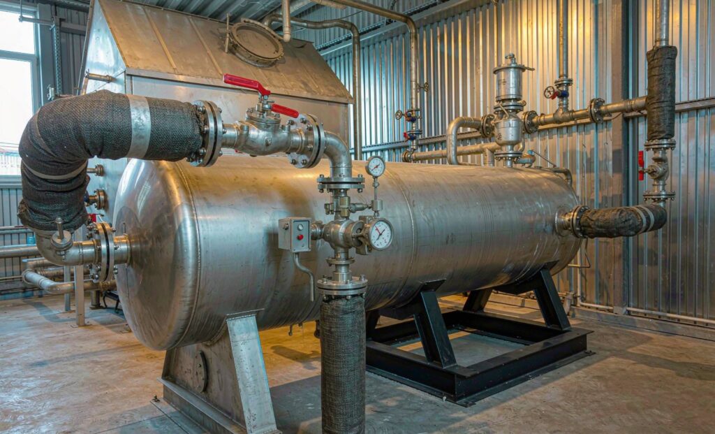
Why Steam Needs Its Own Sizing Method
A shell and tube heat exchanger for steam is not a liquid-to-liquid exchanger with a different fluid name written on the datasheet. Steam condenses at a constant temperature, releases a very large amount of energy per kilogram, and turns into condensate that has to leave the unit under control. Get the thermal calculation right and the mechanical design wrong and the exchanger will still flood, hammer and corrode its way through a tube bundle in two or three seasons.
Steam is still the most common heating medium in food processing, laundries, HVAC plants, district heating substations, paper mills and chemical plants, and the sizing mistakes are remarkably consistent. This guide covers what actually changes when the hot side is condensing steam: how to size a shell and tube heat exchanger for steam, which side the steam belongs on, and why the condensate line decides the service life of the unit.
Sizing a Shell and Tube Heat Exchanger for Steam
The calculation starts with the same equation as any exchanger, but each term behaves differently when one side is condensing.
Step 1: Fix the duty from the cold side
Always calculate the heat load from the secondary (water) side, where flow and temperature rise are measured and known: Q = m · cp · ΔT. A flow of 1 kg/s of water heated from 10 degrees C to 80 degrees C needs about 293 kW. Working from the steam side invites errors, because steam flow is rarely measured accurately and the dryness fraction is usually unknown.
Step 2: Work the LMTD with a condensing hot side
With saturated steam, the hot-side temperature is constant — it is the saturation temperature at the steam space pressure. That simplifies the LMTD to the logarithmic mean of the two terminal differences between the steam temperature and the water inlet and outlet temperatures. Take a 1000 kW duty with steam condensing at 170 degrees C and water heated from 60 to 95 degrees C. The terminal differences are 110 K and 75 K, giving an LMTD of roughly 92 K. Note the word saturation: superheated steam makes the calculation harder and the heat transfer worse, because the desuperheating section has a poor coefficient compared with the condensing section.
Step 3: Sanity check the overall coefficient
Published U-values let you catch an unrealistic proposal in a few seconds. For a clean shell and tube unit with steam condensing on the shell side and water on the tube side, 1,500 to 4,000 W/m²K is normal. A plate exchanger in the same duty will show a higher figure, because the corrugations generate turbulence at much lower velocities. If a supplier quotes a U-value well outside these ranges, the first question is what fouling resistance was used — a clean coefficient is not a design.
Step 4: Add a real fouling allowance and a capacity margin
Two resistances matter: the steam side, typically 0.00009 m²K/W for clean condensate, and the tube side, 0.0001 to 0.0002 m²K/W for softened water and 0.0003 to 0.0005 for hard municipal water. Applied correctly, they may add 25 to 40 per cent to the required area compared with the clean calculation. Then add a capacity margin of 15 to 25 per cent for load swings and start-up. A proposal dramatically smaller than your own hand calculation is not a bargain.
Step 5: Check the operating pressure, not the rated pressure
At part load, less heat transfer means less condensing, which means the steam space pressure drops below the supply pressure. The exchanger finds its own operating point. That lower pressure matters for two reasons: it changes the saturation temperature used in the LMTD, and it is what the steam trap must work against. Undersizing the surface to save money pushes the operating pressure down and can destroy the pressure differential across the trap.
Which Side Does the Steam Go On?
Convention answers this, and the convention is usually right for good reasons.
| Decision | Normal arrangement | Reason |
|---|---|---|
| Steam path | Shell side, condensing | Large volume for vapour, easy drainage to the lowest point, no tube-side pressure penalty from a two-phase fluid |
| Water path | Tube side | High velocity across the tubes keeps the coefficient up and limits scale; easier to inspect and clean |
| Steam on the tube side | Only for high water pressure or dirty steam | Condensate removal from a tube bundle is harder and the tube-side pressure rating drives cost |
| Connections | Steam in high, condensate out low | Gravity drainage; a low inlet traps liquid and causes water hammer |
Keep water velocity in the tube side between about 1 and 2 m/s. Below 1 m/s, sludge and iron oxide settle out and the unit fouls from the inside. Above 2 m/s on carbon steel, erosion at the tube inlets starts to matter.
Plate or Shell and Tube for a Steam Duty?
Both are used, and the choice turns on pressure, temperature and cleanliness rather than efficiency.
- Gasketed plate — compact, low hold-up volume, tight approach temperatures, and the surface can be changed later by adding plates. The limits are the gasket material and the plate channel: sudden pressure spikes and poor steam distribution can damage plates, and narrow channels foul in hard water service. Typical water-side velocity is 0.3 to 1.0 m/s.
- Shell and tube — higher design pressures, a shell that tolerates steam hammer and thermal cycling far better, and tubes that can be cleaned mechanically with the cover removed. Larger footprint and a higher steam inventory.
For saturated steam up to about 10 bar g in clean water service, a plate unit is normally the better optimisation. Above that, or where the water is hard and the plant will clean tubes with a lance, the shell and tube exchanger is the durable answer.
Condensate: Where Most Steam Exchangers Actually Fail
Thermal design decides whether the exchanger meets the duty. Condensate management decides whether it survives.
Stall and condensate backpressure
Stall happens when the pressure in the steam space falls to the backpressure of the condensate return system. At that point there is no differential pressure to push condensate out, the condensate backs up into the shell, and the exchanger floods. Performance becomes erratic, the secondary outlet temperature hunts, and corrosion accelerates because wet steam and oxygen sit against the tubes. Stall usually appears at part load, so a unit that worked perfectly in commissioning can flood every night and nobody connects the two.
Sizing the steam trap
Trap capacity is not the steady-state condensate load. It is the load during warm-up, which is several times higher, and it is set by the differential pressure available — including any lift in the condensate line and any pressure in the return header. A rule of thumb used across process plants: size for 2 to 3 times steady-state load for general process duty, and up to 5 times where the unit starts from cold each day. For a modulating process heat exchanger, a float and thermostatic trap handles varying condensate flow far better than a thermostatic trap, with a smaller thermostatic trap or an automatic air vent in parallel to clear air quickly at start-up.
Two failure modes, two consequences. A trap failed open bleeds live steam quietly into the return line and can run for years undetected. A trap failed closed floods the exchanger, stops the process and gets fixed within hours. The invisibly expensive one is the failed-open trap, which is why a steam trap survey pays for itself faster than almost any other maintenance activity on a steam plant.
Air and non-condensable gases
Non-condensable gases are the quiet performance killer. Air that is not vented collects at the coldest part of the condensing surface as a thin insulating film and can cut the effective coefficient by half or more. Every steam heat exchanger needs a high-point air vent, and every shell needs a vent connection that is actually used rather than capped at commissioning. Poorly treated feedwater also carries carbon dioxide into the steam, which dissolves into condensate and forms carbonic acid — the standard cause of corroded condensate return lines and, eventually, tube failure.
Materials and Construction for Steam Service
Carbon steel shells with stainless or copper alloy tubes cover most steam-to-water duty. The materials mistake that recurs most often in site reports is not on the steam side at all: it is on the condensate side, where the same carbon steel specification is reused for a wet, oxygen-bearing, mildly acidic service. If the exchanger has a separate condensate subcooling duty, treat it as a different corrosion problem and specify accordingly. Where raw water or chlorides above 200 ppm are involved, standard 316L will pit and a duplex or titanium tube surface is the durable choice.
Enquiry Checklist for a Steam Exchanger
- Secondary flow rate, inlet and outlet temperature, and the duty in kW.
- Steam supply pressure in bar g, and whether it is saturated or superheated, with the degree of superheat.
- Design pressure and temperature for both sides, independently.
- Condensate return arrangement: gravity, lift height, pumped return, or vacuum, and the return header pressure.
- Fouling resistance for the water side, based on the actual water chemistry.
- Maximum allowable pressure drop on the water side, as a hard number.
- Whether the duty is constant or modulating, and the minimum turndown.
- Access space for tube cleaning and the intended cleaning method.
If you also want to check the thermal numbers before the enquiry goes out, our step-by-step LMTD sizing guide works through the same calculation in detail. Steam exchangers appear in most of the sectors we list on the applications by industry pages, from food and beverage plants to district heating substations, and the product range covers both shell and tube and gasketed plate construction for steam and hot water duty.
The Short Version
Sizing a shell and tube heat exchanger for steam is straightforward as long as three things are treated as design inputs rather than afterthoughts: the real outlet temperature you need at part load, the pressure drop available across the steam trap including static lift, and the fouling resistance of the actual water in the plant. Get those right and the condensate drains, the coefficient stays where the calculation said it would, and the tubes last.
Zhenggong Cooling and Heating Equipment Co., Ltd builds shell and tube, plate and air-cooled heat exchangers at a 35,000 m² facility in Shandong, China, and holds D1/D2 pressure vessel certification together with ISO 9001 and ISO 14001 — relevant for steam duty, because the shell is a pressure boundary. Send the duty, the steam conditions and the condensate arrangement, and we will return a thermal design with the trap differential checked. Use the contact page for a quotation.
Last updated: October 2026.
Source: Spirax Sarco steam engineering guidance on stall and steam trap selection; TEMA Standards for mechanical design.