
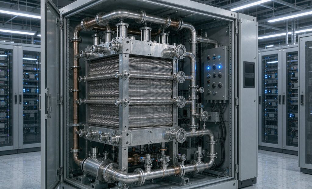
A data center liquid cooling heat exchanger is the component that moves heat out of the technology cooling loop and into the facility loop without ever mixing the two fluids. In a direct-to-chip installation it sits inside the coolant distribution unit (CDU) and quietly fixes three things the whole hall depends on: the rack inlet temperature, the pump head available on both sides, and the coolant quality that reaches the cold plates. With AI cabinets now drawing 60 kW to well over 100 kW each, that exchanger has stopped being a 200 kW accessory and become a multi-megawatt design decision.
This guide covers the data set to fix before anyone quotes a unit, the approach temperature and pressure drop trade-off that decides whether the loop stays stable, and the material choices that determine whether the exchanger is still performing in ten years. It is written for the engineer preparing a CDU enquiry, not for a catalogue.
What a Data Center Liquid Cooling Heat Exchanger Does Inside a CDU
A CDU is a packaged pump-and-exchanger skid. Coolant returns from the rack manifolds warm, passes through a strainer and a flow meter, gives up its heat across the exchanger, and returns to the cold plates at the temperature the IT equipment manufacturer specified. The exchanger is one part of that package, but it is the part that sets the thermal budget.
Three functions are performed across the plate pack or shell:
- Heat transfer from the warmer technology loop into the cooler facility loop.
- Hydraulic separation, so the IT-side pumps are not asked to overcome the resistance of chillers, cooling towers and long facility pipework.
- Fluid isolation, keeping treatment chemicals, glycol, biological growth and 20-year-old steel pipe debris away from cold plates and quick-connects.
That third function is the one that gets under-designed. The facility loop may run 30 % propylene glycol with an inhibitor package selected for a cooling tower; the technology loop may be specified as filtered, low-conductivity water with a chloride limit set by the server vendor. The exchanger is the only place where those two contracts meet, and it has to honour both.
The Two Loops, and Why They Stay Separate
The technology (secondary) loop
From the CDU to the rack manifolds to the cold plates and back. Its chemistry is dictated by the IT equipment — usually a closed, treated water or diluted glycol loop with tight limits on conductivity, chloride, hardness and suspended solids. Its temperature programme is usually aggressive: a 40 °C supply and 50 °C return is common on warm-water designs, which pushes the required approach on the facility side down to a few degrees.
The facility (primary) loop
From the CDU to whatever rejects the heat: a cooling tower, a dry cooler, an existing chilled-water plant, an adiabatic cooler, or a combination with a mode-changeover valve. This loop is where the site’s water availability, ambient design temperature, noise limits and redundancy philosophy live.
Because the facility side determines the temperatures actually available to the CDU, it has to be chosen before the exchanger is sized. A tower that can deliver 30 °C condenser water supports a very different rack inlet temperature from a dry cooler designed for a 38 °C dry bulb summer. Sizing the exchanger first and hoping the rejection equipment catches up is the single most expensive ordering mistake in liquid-cooling projects.
Sites that reject heat with air rather than evaporation are covered in more depth in our guide to dry coolers for data center cooling and water-free heat rejection.
The Numbers to Fix Before a CDU Heat Exchanger Is Quoted
Two quotations with the same nominal capacity are rarely comparable. Assemble this data set first — every missing item changes plate count, connection size, pressure drop and price:
- Present and future IT heat load, at peak and at partial load, including a stated growth allowance.
- Supply and return temperature on the technology loop and the facility loop, for the design case and the worst-case ambient case.
- Flow rate on both sides, or the flow the selected CDU pumps can actually deliver.
- Coolant type and concentration (water, glycol–water, dielectric), plus viscosity at the lowest expected operating temperature.
- Maximum allowable pressure drop on each side, separately. One number for both sides is a red flag in a tender.
- Design pressure and design temperature, with the applicable code and any client specification.
- Water-quality limits: conductivity, pH, chloride, hardness, filtration rating, inhibitor chemistry.
- Duty/standby philosophy — N+1 pumps, dual exchangers, isolation valves, bypass strategy.
- Floor space, service clearance for opening a plate pack, lifting route, drain and vent points.
- Documentation required: material certificates, pressure-test records, hydraulic curves, welding procedure specifications.
If a supplier offers a fixed unit from stock before asking about half of these, the quotation is a price, not a selection.
Approach Temperature: The Number That Sets Rack Inlet Temperature
Approach temperature is the closest difference between the two streams anywhere in the exchanger. It drives surface area, and surface area drives cost, footprint and pressure drop. In liquid cooling it is also the number that decides whether the rack inlet temperature can be met on the hottest day of the year.
| Approach at design point | What it costs and requires | Practical use |
|---|---|---|
| 1 °C | Very large surface area, high plate count, clean closed-loop water, generous pump head, strict filtration. | Only defensible when the IT specification leaves no margin at all. |
| 2–3 °C | Realistic for modern CDUs. Needs verified pressure drop and a defined fouling plan. | The working target for most direct-to-chip projects. |
| 5 °C or more | Smaller, cheaper, more forgiving of fouling and of facility-side temperature drift. | Sensible where the IT supply temperature target is conservative. |
A single tight approach at one end of the unit is achievable in a clean closed loop. It is not achievable with untreated make-up water, no filtration and a strainer that nobody cleans. Where a quotation claims a 1 °C approach with few plates, ask for the full thermal selection rather than the summary offer sheet — the summary hides the fouling factor and the pressure drop.
Pressure Drop, Viscosity and Pump Energy
Higher plate corrugation means more turbulence, a higher overall heat transfer coefficient, and more pressure loss. Since pump power scales roughly with flow cubed and directly with head, a unit that meets the duty while doubling the loop pressure drop can cost more in electricity over its life than it saves in capital cost. State the allowable pressure drop on each side and check the selected plate pattern against it before the order is placed.
Viscosity is the trap in glycol and dielectric loops. A 30 % propylene glycol solution has a noticeably higher viscosity than water, and dielectric fluids are higher again, often by a factor of several. Higher viscosity thickens the boundary layer, reduces the heat transfer coefficient, and raises pressure drop at the same flow. A selection performed on water properties and then operated on glycol will miss its duty. Insist that the thermal calculation uses the coolant’s properties at the actual mean operating temperature, not at 20 °C.
Plate, Brazed or Shell and Tube?
| Type | Strengths | Where it fits |
|---|---|---|
| Gasketed plate and frame | Highest heat transfer per unit volume, tight approach, openable for inspection and cleaning, capacity can be extended later by adding plates. | The default for CDU liquid-to-liquid duty where space is tight and maintenance access exists. |
| Brazed plate | Compact, no gaskets, higher pressure rating, no elastomer to age. | Smaller CDUs, sealed circuits, and loops where a leak path to atmosphere must be eliminated. |
| Shell and tube | Robust, tolerant of debris and thermal shock, high design pressure, easy to clean tube-side, well understood by every site maintenance team. | Larger duties, dirty or unfiltered facility water, high pressures, and retrofits where plant crews already maintain shell and tube equipment. |
| Welded / semi-welded plate | Gasket-free on one side while remaining openable on the other. | Asymmetric duties where one loop is aggressive or very high pressure, for example a tall building’s chilled-water circuit on one side. |
Gasketed plate units are the usual first choice for CDU duty because the approach is tight and the footprint matters. The counter-argument is maintenance: a gasketed pack needs space to open, a spare gasket set, and a crew that knows the tightening sequence. In a colocation hall where service access is planned around racks rather than around plate packs, shell and tube occasionally wins on operability alone. The comparison of how the two families behave in practice is set out in shell and tube versus plate heat exchangers.
Water Quality and Material Selection
Chloride is the deciding variable for plate material. The technology loop is normally well-controlled, so 316L stainless is adequate, and titanium is specified where the facility water is brackish, where free cooling brings in raw or tower water, or where water treatment has historically been inconsistent.
| Circuit condition | Plate / tube material | Gasket |
|---|---|---|
| Treated, filtered closed loop with inhibited water | 304 or 316L stainless | EPDM |
| Closed loop with glycol, elevated temperature | 316L stainless | EPDM, or FKM above the EPDM temperature limit |
| Tower water or poor-quality make-up | 316L, titanium where chlorides are high | EPDM |
| Seawater, brackish or reclaimed water | Titanium | EPDM |
| Dielectric fluid | Titanium or specified alloy, subject to fluid compatibility testing | Per fluid supplier data |
Water treatment belongs in the heat exchanger specification, not in a separate facilities document. Conductivity, pH, chloride, hardness and filtration rating should be stated, monitored after commissioning, and re-checked at the first 12-month inspection rather than assumed from the start-up sample. Scaling, biological growth and cold-plate deposits all begin with a water chemistry that was never defined.
Redundancy: Designing for the Failure Nobody Plans For
Mission-critical cooling has to work at design load, at partial load, during planned maintenance, and through credible equipment failure. A heat exchanger design that only holds the rack inlet temperature under normal conditions is incomplete. The design should state, in writing, what happens if a pump trips, a strainer blinds, one exchanger is isolated, a sensor drifts, or a rack leak alarm trips.
- Define N+1 or 2N philosophy for pumps, exchangers and controls before procurement, not during commissioning.
- Provide differential pressure and temperature measurement across the exchanger so performance loss can be diagnosed rather than guessed.
- Show isolation, bypass, drain, vent and sampling points on the P&ID.
- Keep realistic service space around pumps, strainers, valves and plate packs.
- Confirm the flushing and water-quality plan with both the CDU supplier and the IT equipment vendor.
Common Selection Mistakes
Buying on capacity alone. Several offers with the same nominal kW can carry entirely different pressure drops, approach temperatures, materials and documentation. Capacity is the least discriminating number in the comparison.
Choosing the rejection equipment last. The facility loop sets the temperatures available to the CDU. Deciding it after the exchanger is sized forces a redesign or an under-performing hall.
Assuming one pressure drop figure covers both sides. Facility-side and technology-side limits are usually different and are set by different owners.
Leaving coolant chemistry undefined. Gasket compatibility, plate material, filtration and cleaning intervals all derive from the coolant specification.
Choosing a unit with no service access. A plate pack that cannot be opened without rigging a rack out of the way will not be opened.
Ordering before the P&ID exists. Vendor battery limits, control philosophy and redundancy cases must be clear before the purchase order.
Sourcing a CDU Heat Exchanger
Data center projects reward a supplier who will quote against a real thermal duty rather than a catalogue range, and who will produce the hydraulic curves and material certificates the technical bid evaluation asks for. Zhenggong Cooling and Heating Equipment manufactures gasketed, brazed and shell and tube heat exchangers at its 35,000 m² facility in Shandong, China, and supports cooling duties across data center, HVAC, refrigeration and industrial process sectors — the industry applications index sets out the sectors served. Pressure-retaining parts are produced under D1/D2 pressure vessel certification, with ISO 9001 and ISO 14001 quality and environmental management; the certificates are listed on the certification page.
The brazed and fusion-bonded plate heat exchanger range covers the compact end of CDU duty, and the wider product range includes gasketed plate and shell and tube units for larger or dirtier facility loops.
Next Step
Send the IT heat load with its growth allowance, both loops’ supply and return temperatures, both flow rates, the coolant and its concentration, the allowable pressure drop on each side, the water-quality limits and the redundancy requirement. With those numbers a CDU exchanger selection, including the thermal calculation and the pressure drop on both sides, can be produced in one pass. Send your design data to Zhenggong for a quotation and ask for the material certificates and hydraulic data to be issued with the offer.