
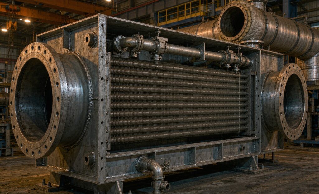
A flue gas heat exchanger sits in the exhaust path of a boiler, furnace or engine and pulls useful heat out of gas that would otherwise leave through the stack. Placed as an economiser, it preheats boiler feedwater; placed as an air preheater it warms combustion air; on a furnace or kiln it preheats a process stream. In every case the physics are simple and the economics are usually strong — but the design constraint that decides whether the unit survives is not thermal at all. It is corrosion at the cold end.
This guide covers how much heat is realistically available, where the acid dew point sets the floor, how condensing and non-condensing designs differ, and which tube geometry to choose for the fuel being burned.
How Much Heat Is Actually Recoverable
Flue gas leaving the convective section of a typical industrial boiler still carries substantial sensible heat, commonly arriving at the economiser between 200 °C and 350 °C. The field rule of thumb used by plant engineers is that boiler efficiency improves by about 1 % for every 20 °C of flue gas temperature reduction.
| Stack temperature reduction | Approximate efficiency gain |
|---|---|
| 20 °C | 1.0 % |
| 40 °C | 2.0 % |
| 60 °C | 3.0 % |
| 100 °C | 5.0 % |
The relationship is not perfectly linear and depends on excess air and gas composition, but it is accurate enough to scope a retrofit or to judge whether a fouled economiser is worth cleaning. Those savings are also usually the largest single efficiency measure available to a plant that has already fixed its combustion settings — the detailed payback method is set out in our guide to modelling waste heat recovery return on investment.
The Acid Dew Point: The Hard Design Limit
Sulphur in the fuel oxidises during combustion and a fraction of it becomes sulphur trioxide, which combines with water vapour to form gaseous sulphuric acid. If any metal surface in the exchanger falls below the acid dew point, that acid condenses directly onto the tube and attacks it. The water dew point and the acid dew point are different figures, and on sulphur-bearing fuels the acid dew point is the controlling one.
| Fuel | Typical sulphur content | Approximate acid dew point |
|---|---|---|
| Natural gas | Negligible | Below 100 °C; the water dew point usually governs |
| Light fuel oil | Low | 120–130 °C |
| Heavy fuel oil | High | 140–160 °C |
| Coal | Variable | 120–150 °C |
Two practical points follow. First, the dew point is not a fixed number — it moves with fuel quality, excess air and moisture, so a single catalogue figure copied from another project is not a safe basis. Second, what matters is the lowest metal surface temperature in the unit, not the average gas outlet temperature. Measuring an acceptable stack temperature does not prove that no tube in the bundle is running cold.
Controls used to keep surfaces above the limit include maintaining a minimum feedwater inlet temperature, return-line mixing or recirculation, a three-way valve arrangement, and bypassing the economiser during start-up and low-load operation. Corrosion is usually worst where the cold fluid enters, in pockets of poor flow, at fin-to-tube joints and anywhere condensate can pool.
Condensing Versus Non-Condensing Designs
A non-condensing economiser is sized so that every metal surface stays safely above the acid dew point. It recovers sensible heat only and leaves the water vapour in the gas untouched. Carbon steel or ferritic alloy tubes are usually adequate, with a corrosion allowance and disciplined operation.
A condensing economiser deliberately drives gas temperature below the water dew point to release latent heat, delivering a further step in efficiency — condensing designs on natural gas can push boiler efficiency beyond 100 % on an LHV basis. The price is construction quality: corrosion-resistant surfaces, a gas-tight casing, sloped surfaces and drains, and a plan for neutralising the acidic condensate that is produced. Condensing designs are practical above all on low-sulphur fuels, where the acid dew point is low and the recoverable latent heat is large.
Choosing Tube Geometry
| Tube type | Characteristics | Best suited to |
|---|---|---|
| Helically finned tubes | Highest surface density and heat transfer coefficient, but prone to progressive fouling in dirty gas | Natural gas and LPG boilers; clean, particulate-free gas |
| Continuous or plate fins | Compact, high area, cleanable by air blowing or sootblowers | Diesel-fired boilers and gases with moderate particulate |
| Bare tubes | Lower surface density but maximum robustness; easy mechanical cleaning | Biomass, heavy fuel oil and process gases with ash or high SO₂ |
| H-type or double-finned tubes | Aligned channel geometry that reduces dust deposition and aids sootblower cleaning | Dirty gas streams where ash accumulation and localised attack combine |
The pattern to avoid is a dense finned bundle in a dirty gas stream. Fins bridge with ash, gas flow is throttled, stack temperature climbs back toward where it started, and the unit quietly stops saving money while still consuming fan power.
Sizing Inputs the Manufacturer Needs
- Flue gas mass flow, in kg/h or Nm³/h, at rated output and at partial load (typically 50 % and 75 %).
- Gas inlet temperature at the economiser, which varies with load.
- Target gas outlet temperature, constrained by the acid or water dew point.
- Fluid flow rate and inlet temperature — on a steam boiler, feedwater typically arrives from the deaerator at 60–105 °C.
- Target fluid outlet temperature, with margin below saturation temperature at working pressure to prevent boiling in the tubes.
- Gas composition: CO₂, H₂O, SO₂, NOₓ, ash and particulate content.
- Allowable pressure drop on both the gas and fluid sides, set by fan and pump capability.
- Cleaning method and access requirements.
The governing equation remains Q = U·A·ΔTlm, in which the log mean temperature difference dominates. Because the flows are usually unbalanced — a large gas mass flow meeting a smaller water or process stream — good counterflow arrangement is essential to keep the required area and the metal temperatures under control.
Fouling and Cleaning Strategy
Two deposit problems dominate maintenance. Gas-side fouling from soot, ash and particulate settles on the outside of tubes and fins, insulates the surface and chokes gas flow. Water-side scale from hard or poorly treated feedwater precipitates inside the tubes and sharply reduces heat transfer while risking tube-metal overheating. Sootblowers, periodic offline gas-side cleaning and disciplined water treatment are the routine defences, and sootblowing itself must be balanced against driving acidic condensate across cold metal. The same insulating mechanism is described for liquid duties in our article on the causes and prevention of heat exchanger fouling.
Thermal Stress and Mechanical Detail
An economiser operates across the largest temperature span in the boiler, and its tubes and casing expand at different rates during start-up and shutdown. If that movement is restrained, the result is fatigue at welded joints or deformation of the headers. Countermeasures include a floating head or sliding tube-sheet arrangement that permits differential expansion, expansion compensators in the connecting pipework, and defined maximum heat-up rates in the operating procedure. On shell and tube construction, the choice between fixed and floating heads is therefore driven by thermal movement as much as by pressure.
A Design Checklist
- Fuel analysis and measured dew point established for the actual fuel and load range.
- Minimum metal surface temperature defined, with margin above the acid dew point.
- Condensing or non-condensing duty chosen deliberately, with the materials that follow from it.
- Tube geometry matched to gas cleanliness, not to the highest available surface density.
- Gas-side and fluid-side pressure drop checked against available fan and pump head.
- Partial-load and bypass control schemes defined, including start-up behaviour.
- Drainage designed with slopes and low-point connections; condensate neutralisation planned.
- Cleaning access and sootblower layout agreed during the mechanical design.
- Differential expansion resolved in the mechanical arrangement, not left to the site.
Recovering the Heat Is Only Half the Job
A flue gas heat exchanger earns its place only if the recovered energy has a continuous use at the right temperature level. Preheating feedwater or combustion air is the classic match because the demand is always present when the boiler runs. Where the recovered heat must be stored or transported, the value drops quickly and the payback stretches. Sizing the unit for the boiler and not for the sink is the most common way these projects under-deliver.
Getting the Unit Built to the Gas
Economiser life is decided by material, geometry and weld quality rather than by nominal duty. Zhenggong Cooling and Heating Equipment designs and manufactures waste heat recovery and flue gas exchangers from its 35,000 m² facility in Shandong, China, in carbon steel, stainless steel, duplex and titanium as the gas chemistry requires, with extended-surface and bare-tube options. Pressure-retaining components are built under D1/D2 pressure vessel certification with ISO 9001 and ISO 14001 management systems, and documentation is issued for project approval — see the certification page for details.
Typical shell and tube configurations and material options for this duty are shown in the stainless shell and tube heat exchanger range, and the engineering services page describes the thermal design and site support that accompany the supply.
Next Step
The design can be fixed quickly once the fuel analysis, gas flow, temperatures and dew point are on the table. Send your boiler and flue gas data to Zhenggong for a quotation, and ask for the minimum metal temperature and the fouling assumptions to be stated explicitly on the datasheet so that the corrosion margin is visible rather than implied.