
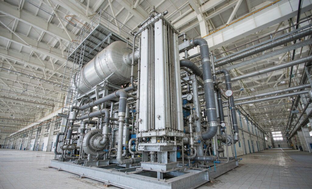
How an MVR Falling Film Evaporator Reuses Its Own Latent Heat
Evaporating a tonne of water takes roughly 620 kWh of latent heat at 70 °C. A multi-effect evaporator pays for a large part of that energy with live steam; an MVR falling film evaporator pays for it with compressor shaft work instead, because it takes the vapour boiled off the product, compresses it enough to raise its saturation temperature by 8–20 K, and condenses that same vapour back on the other side of the tube wall.
At steady state the only continuous energy input is the compressor, and the heat exchanger at the centre of the loop has to be sized for a very small effective temperature difference. That is where the design either works or does not. This guide covers falling film versus forced circulation, the numbers that size the system, compressor selection and the material rules that keep a high-chloride brine from destroying the tubes.
The Working Loop, Stage by Stage
- Feed conditioning. Feed passes through a preheater, usually recovering heat from hot condensate and concentrate, and reaches a temperature close to the boiling point of the evaporator body.
- Falling film distribution. Liquid is distributed across the top tube sheet and flows down the inside of the tubes as a thin film, driven by gravity with residence times of seconds. The shell side carries condensing compressed vapour.
- Vapour-liquid separation. Secondary vapour rises into a separator or vapour body with a demister. Carryover must stay below roughly 0.1% of vapour mass — droplets erode compressor impellers and trip vibration protection.
- Mechanical recompression. A centrifugal, screw or roots compressor lifts the vapour pressure. This is the only significant power input in the loop.
- Condensation and heat release. The compressed vapour condenses on the shell side and releases its latent heat through the wall to the falling film — which boils again. The cycle is closed.
- Distillate and concentrate discharge. Distillate leaves as condensate for reuse; concentrated brine leaves from the bottom, either for further crystallisation or for discharge.
Because the boiling point is held at 60–80 °C by operating under vacuum at roughly 0.2–0.5 bar absolute, scaling risk and thermal degradation both fall, and the wall temperature difference stays small enough that a standard austenitic grade can sometimes replace a more exotic alloy.
Falling Film Versus Forced Circulation
| Criterion | Falling film | Forced circulation | Plate evaporator |
|---|---|---|---|
| Heat transfer coefficient | High, for low-viscosity liquids | Moderate — relies on pumped velocity | Highest for clean liquids |
| Residence time | Seconds — suits heat-sensitive product | Long, recirculated | Seconds |
| Fouling and scaling tolerance | Moderate; needs even film distribution | High — 1.5–3.5 m/s sweeps the surface | Poor; narrow channels block |
| Viscosity limit | Roughly 20 mPa·s above which the film breaks up | No practical limit | Low |
| Crystallising duty | Not suitable on its own | Standard choice | Not suitable |
| Typical use | Wastewater concentration, dairy, juice, pharma, desalination | High-salt brine, crystallisation, ZLD trains | Clean food, dairy, pharma streams |
The practical combination in most zero-liquid-discharge trains is falling film for the bulk evaporation stage and forced circulation for the final concentration and crystallisation stage, where solids and viscosity rise beyond what a gravity film can handle. Where the product is a clean, low-fouling liquid, a gasketed or brazed plate heat exchanger gives a higher coefficient in a smaller package — but only if it can be opened or cleaned when it fouls.
The Numbers That Size an MVR System
Specific energy consumption is the first figure a buyer should compare, and the honest comparison is against a multi-effect train rather than against a single-effect evaporator.
| Configuration | Energy per tonne of water evaporated | Relative operating cost |
|---|---|---|
| Single-effect (SEE) | 1,000–1,200 kg live steam | Highest |
| Triple-effect (MEE) | 350–420 kg live steam | Moderate |
| Thermal vapour recompression (TVR) | Around 30–50% of SEE steam, plus 4–6 bar motive steam | Low where high-pressure steam is free |
| MVR, centrifugal compressor | 18–26 kWh electrical | Lowest where electricity is reasonably priced |
| MVR, roots or screw compressor | 22–30 kWh electrical | Slightly higher, used on small or high-pressure-ratio duty |
A worked estimate. Take 50 m³/day of wastewater at 50 g/L total dissolved solids to be concentrated to 250 g/L. Solids in and out are conserved, so concentrate volume is 10 m³/day and the water to evaporate is 40 m³/day, or about 1.67 t/h. With a 15–20% margin, specify a 2.0 t/h evaporator. At 20 kWh per tonne, compressor power is roughly 40 kW, giving about 960 kWh per day — a small fraction of the steam cost of the equivalent multi-effect train, which is why MVR payback commonly lands in the two-to-three-year range despite a capital cost around 1.5 to 2 times a conventional evaporator.
The capital and operating trade-off is the same structure as any waste heat recovery investment: the compressor is the recurring cost, and its efficiency is set almost entirely by how small a temperature difference the heat exchanger can achieve.
Effective Temperature Difference Decides the Surface Area
The evaporator area follows the usual relationship:
A = Q / (K × ΔTeff)
where Q is the heat load and K is the overall coefficient. The catch is that the effective difference is not the compressor lift. It is the lift minus everything the process consumes:
ΔTeff = ΔTcompressor − BPE − hydrostatic head loss − fouling allowance
- Boiling point elevation (BPE) grows with dissolved solids and can reach several kelvin in saturated brine, consuming lift before any heat flows.
- Hydrostatic head loss comes from the liquid column above the boiling surface — a reason to keep the liquid level in the vapour body tight and the bundle shallow.
- Fouling allowance is a design choice, not an accident. A small allowance lets the plant start efficiently and degrade quickly; a large one costs area from day one but holds capacity for years. This is why the fouling mechanisms and fouling factors in a design review matter more on MVR duty than on any ordinary water-cooled exchanger.
Because area is inversely proportional to effective difference, a design that runs at 8 K needs roughly half the surface of one at 4 K for the same duty — but the compressor pays more to provide that lift. There is an optimum, and it is normally found by comparing capital against specific energy consumption across a few candidate lifts rather than by adopting a default.
Compressor Choice Sets the Whole Design
| Compressor | Evaporation capacity | Pressure ratio | Comment |
|---|---|---|---|
| Centrifugal, single stage | Above roughly 5 t/h | Low | Best specific power, 65–75% isentropic efficiency, sensitive to vapour wetness |
| Centrifugal, multistage | 2 t/h upward | Moderate | Handles larger lift at the cost of more stages and more maintenance |
| Screw | Small to medium | High | Tolerates higher BPE and load swings; oil circuit and seal maintenance required |
| Roots / multistage roots | Small | Low per stage | Used for small duty and retrofit packages; noisier, lower efficiency |
Continuous, near-constant duty favours a centrifugal machine and a falling film exchanger. Duty that swings widely, or a brine with a high boiling point elevation, pushes the selection towards a screw compressor and a forced-circulation body — a pairing that is less efficient but far more forgiving.
Scaling, Cleaning and Material Selection
Falling film evaporators foul differently from flooded exchangers. Scale forms where the film is thinnest and evaporation is most intense — typically the upper third of the tubes — and a blocked distributor causes dry patches that scale almost immediately.
- Design for cleanability from the start: removable headers, full access to the tube sheet, and a distributor that can be inspected without dismantling the bundle.
- Run a CIP regime on condition, not on a calendar. Trigger cleaning when the coefficient drops by about 5%, or when the required compressor lift rises to hold duty. Typical chemistry is 1–3% caustic at 70 °C for organic deposits, 1–3% nitric acid for mineral scale.
- Choose materials by chloride level and temperature. Chloride-free duty can use 304; chloride-bearing streams generally need 316L or duplex 2205; above roughly 500 mg/L chloride at over 80 °C, titanium or a super-duplex grade is the safe choice. See the full comparison in our tube material selection guide.
- Protect the compressor: separator efficiency, droplet carryover limits, and a demister that is inspected on the same frequency as the heat exchanger.
Specification Checklist for an MVR Falling Film Evaporator
- Feed composition, density, viscosity and pH at operating temperature
- Feed rate and the target concentrate concentration and discharge rate
- Evaporation capacity in t/h, with design margin stated
- Boiling point elevation at the design concentration
- Operating boiling temperature and pressure, and the vacuum source
- Heat load, overall coefficient basis and the fouling allowance used
- Required heat transfer area and tube geometry, including tube length and diameter
- Compressor type, pressure ratio, isentropic efficiency and installed power
- Steam quality or vapour temperature entering the compressor, plus superheat management
- Separator type and the maximum permissible droplet carryover
- Tube, shell, tubesheet and gasket materials with the chloride and temperature limits behind them
- CIP arrangement, cleaning chemistry and cleaning frequency assumptions
- Condensate reuse requirement, including any polishing stage
- Instrumentation and control philosophy: level, density, conductivity, compressor surge protection
- Certification and documentation scope where the exchanger is a pressure vessel
The Bottom Line
An MVR falling film evaporator succeeds or fails on the effective temperature difference. Size the exchanger for the smallest difference the compressor can deliver economically, account honestly for boiling point elevation and fouling, choose the tube material against the chloride level rather than the purchase price, and design the CIP route before the tube sheet is drilled.
Zhenggong Cooling and Heating Equipment manufactures falling film and flooded evaporators, shell and tube, plate and air-cooled heat exchangers from a 35,000 m² facility in Shandong, China, holding D1/D2 pressure vessel certification with ISO 9001 and ISO 14001 systems, and supplies process and refrigeration customers worldwide. For an MVR or evaporation duty, send the feed analysis and duty to the engineering team. The falling film evaporator range and the complete product portfolio cover the rest of the heat transfer scope in the same train.