
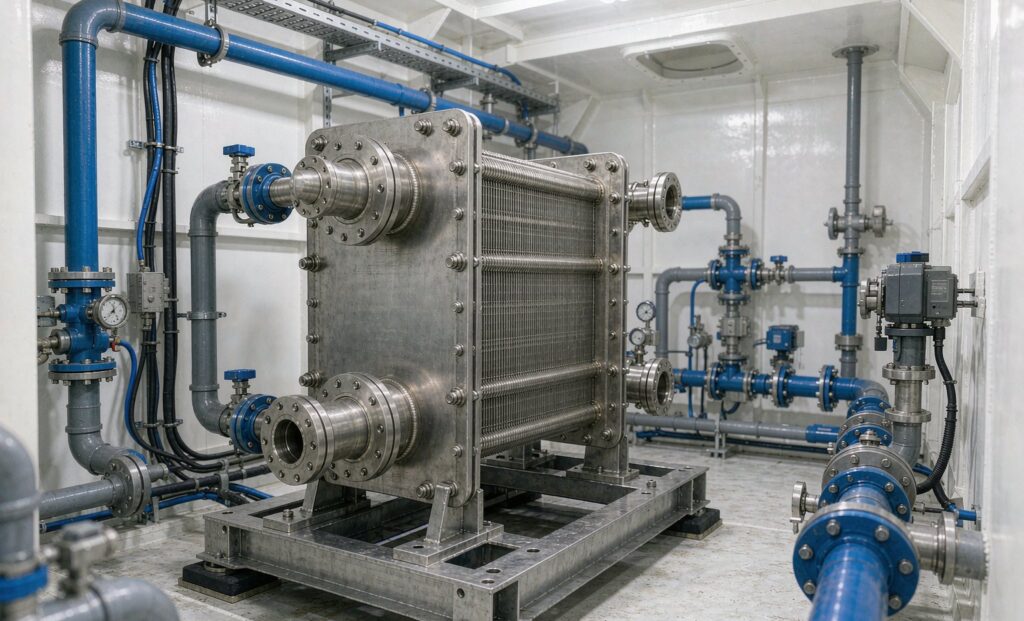
What an Electrolyzer Cooling Heat Exchanger Has to Remove
An electrolyzer cooling heat exchanger is sized by an uncomfortable fact: a modern electrolysis stack converts roughly 65% of its electrical input into hydrogen and releases the other 35% as heat. That heat has to leave the stack continuously, at a controlled temperature, or the membrane dries out, the electrodes degrade and the stack’s efficiency falls away over its service life. For a plant producing 1,000 Nm³ of hydrogen per hour, the cooling duty is typically 3,500 to 4,500 kW — a heat rejection load comparable to a mid-sized industrial chiller plant, concentrated in a loop that carries deionised water at a conductivity measured in fractions of a microsiemens.
That combination — large duty, high purity, tight temperature control, and often 30 bar of operating pressure — makes this one of the few heat exchanger applications where the standard product catalogue is genuinely the wrong place to start. This guide sets out the heat load arithmetic, the circuit architecture, the material rules that decide whether a unit lasts five years or twenty, and the data an RFQ needs to be useful.
Two Stacks, Two Different Cooling Problems
PEM and alkaline electrolysers are both electrochemical stacks cooled by a liquid loop, and beyond that they have little in common. Specifying one exchanger for both, or assuming the alkaline experience transfers to PEM, is the most common early mistake in green hydrogen projects.
| Parameter | PEM electrolyser | Alkaline (AEL) electrolyser | Solid oxide (SOEC) |
|---|---|---|---|
| Stack operating temperature | 50–70 °C | 60–90 °C | 700–850 °C |
| Coolant | Deionised water, ultrapure | KOH solution, typically 25–32 wt% | Not liquid-cooled at the stack; gas-to-liquid recovery |
| Typical operating pressure | Up to 30 bar, some designs higher | Atmospheric to about 30 bar | Near atmospheric |
| Contamination sensitivity | Extreme — metal ions poison the membrane | Moderate, but caustic attacks many alloys | Low on the gas side, high thermal cycling |
| Heat to remove | Roughly 25–30% of input power | Roughly 20–25% of input power | Recovered from hot product gas |
| Exchanger that fits | All-welded 316L plate or shell and tube, copper-free | Nickel or nickel-alloy wetted parts, welded on the caustic side | High-temperature gas cooler, not a plate unit |
The PEM row is the one that catches buyers. The stack coolant is not merely clean water; it is water held at a conductivity low enough that it will not carry ions into the membrane. Every material decision in the cooling loop follows from that, and it eliminates the cheapest and most widely available plate exchanger construction outright.
The Three-Circuit Architecture
Nearly all commercial electrolyser cooling systems are built as three circuits in series, with a heat exchanger at each boundary. Understanding which one you are specifying prevents the classic error of buying an industrial plate unit for a duty that needs an ultrapure one.
Circuit 1 — the stack loop
Deionised water circulates from the stack through a pump, a filter, an ion-exchange bypass and the primary side of the heat exchanger. Conductivity is monitored continuously, and a rise above setpoint triggers an alarm and often a derate. The loop is small in volume, runs at the stack’s operating pressure, and must be built from materials that do not shed ions: 316L stainless, PVDF or EPDM, with no copper, brass, carbon steel or galvanised components anywhere in contact with the fluid.
This circuit is where the exchanger’s material choice is decided. It is also where a leaking gasket becomes a stack failure rather than a maintenance item, because the contaminant enters the electrolyte directly.
Circuit 2 — the secondary cooling loop
A separate loop, usually water with glycol where freezing is possible, carries heat away from the primary exchanger and delivers it either to a heat rejection system or to a heat user. This is the circuit that physically separates ultrapure water from the plant’s utilities, and it is why the primary exchanger is normally an all-welded or semi-welded unit rather than a gasketed one: the fewer elastomer seals between the two, the better.
Circuit 3 — heat rejection or recovery
The final stage is a dry cooler, cooling tower, chiller or — where a heat user exists — a heat recovery exchanger feeding a district heating network, a desalination plant or a feedwater preheater. This circuit is conventional industrial cooling and can use standard equipment.
Sizing the Electrolyzer Cooling Heat Exchanger
Three numbers decide the selection. As with most process exchangers, the failure mode is not an undersized duty but a duty quoted at the wrong conditions.
| Input | How to establish it | Why it governs the design |
|---|---|---|
| Stack heat rejection | Input power × (1 − stack efficiency), or 3.5–4.5 kW per Nm³/h of hydrogen produced | Sets the duty. Use the stack’s guaranteed efficiency at end of life, not beginning of life — degradation raises the heat load. |
| Stack temperature window | Manufacturer’s inlet and outlet limits, typically a 5–10 K rise across the stack | Fixes the primary flow rate and the maximum approach the exchanger may impose. PEM stacks often allow only ±1 K control at the inlet. |
| Available cooling medium temperature | Dry cooler approach in summer ambient, or chilled water supply | Sets the secondary inlet temperature and therefore the LMTD. Summer ambient, not annual average, is the design case. |
| Allowable pressure drop | Set by the circulating pump curve on each side | Trades directly against velocity and surface area; on the primary side it also affects the purity loop’s pump energy. |
| Design pressure | Stack operating pressure plus margin, and any differential case | Above roughly 16 bar, gasketed construction stops being the default and welded units are required. |
Worked example: a 5 MW PEM plant at 65% stack efficiency rejects about 1,750 kW. With a stack outlet at 65 °C, a 8 K rise across the stack and a secondary supply at 40 °C in summer, the exchanger sees roughly 65/57 °C on the primary and 40/48 °C on the secondary. That is an LMTD near 16 K, which is comfortable — but only if the secondary supply really is 40 °C in July. Substitute a 48 °C summer ambient with a dry cooler and the LMTD collapses to about 11 K, and the required surface area rises by nearly half. That single substitution is the most common reason a cooling system underperforms in its first summer.
Design margin should be modest and deliberate. Oversizing the exchanger costs little in capital but shifts the primary flow to a lower velocity, which can hurt temperature control response. A 10–15% margin on duty, with the approach temperature held as a hard constraint, is a better specification than a 30% margin on area.
Why Copper Brazing Fails on a DI Water Loop
The most widely used plate heat exchanger in the world is copper-brazed: stainless plates, copper foil between them, brazed in a vacuum furnace. It is compact, cheap and thermally excellent. It is also unsuitable for an electrolyser primary loop, and the reason is not corrosion in the conventional sense.
Copper in contact with deionised water leaches. Deionised water is aggressive precisely because it has no dissolved solids — it will dissolve the oxide layer on copper and carry copper ions into the loop. Those ions raise conductivity, which the plant’s instrumentation registers within days, and in a PEM stack they migrate to the membrane and degrade it permanently. The result is not a leaking exchanger; it is a stack whose efficiency falls and which cannot be recovered by cleaning.
There are three acceptable constructions for the primary side:
- All-welded or fusion-bonded stainless plate. No braze filler, no elastomer, highest integrity, compact. Not openable for mechanical cleaning, so it suits clean ultrapure water with filtration upstream.
- Semi-welded plate. Welded cassette on the primary side, gasketed on the secondary. Serviceable on the utility side and sealed on the sensitive side. This is the usual choice for larger plants.
- Shell and tube in 316L. Higher pressure capability, tolerant of thermal cycling and differential expansion, and easy to inspect. Larger and heavier, which matters on skid-mounted plants.
Note also that “hydrogen-rated” is not a material property. An exchanger handling deionised water in a hydrogen plant is not necessarily suitable for a hydrogen gas stream, which brings its own requirements around sealing, permeation and pressure cycling. State which fluid is actually in contact with the surfaces.
Materials by Electrolyte
Material selection is driven by the electrolyte, not by the hydrogen. The two mainstream technologies demand quite different answers.
| Circuit | Recommended wetted material | Avoid | Reason |
|---|---|---|---|
| PEM stack loop (DI water) | 316L stainless, titanium for aggressive secondary water | Copper, brass, carbon steel, galvanised parts | Ion leaching raises conductivity and poisons the membrane |
| PEM secondary loop (water/glycol) | 316L, or copper-brazed plate if fully isolated | Aluminium, mild steel | Glycol degradation products are acidic and attack aluminium |
| Alkaline stack loop (25–32% KOH, 60–90 °C) | Nickel 200/201, or nickel-plated and welded construction | 316L in hot concentrated caustic, copper alloys, aluminium | Caustic at temperature causes stress corrosion cracking in austenitic stainless |
| Alkaline secondary loop | 316L, EPDM or PTFE gaskets | NBR in continuous hot service | Gasket life, not corrosion |
| Seawater-cooled variant | Titanium plates or tubes, super duplex where chlorides are controlled | 316L above about 1,000 mg/l chloride with residual chlorine | Pitting and crevice corrosion |
For alkaline service the nickel rule is not negotiable above roughly 80 °C and 20% KOH. Many projects specify 316L because it is the default stainless and cheaper, and discover the issue at the first inspection. If the caustic loop is dilute, cool or intermittent, 316L may be defensible; it should be a documented decision, not a default.
Heat Recovery: When the Waste Heat Is Worth Money
Electrolyser heat is low grade — typically 50–80 °C — but it is continuous, which makes it more valuable than a batch process heat source. Three uses are proven:
- District heating. A 5 MW stack rejecting 1,750 kW can supply a meaningful number of dwellings, but only if the network’s return temperature is low enough. Fourth-generation networks at 45–55 °C return are the realistic target; a 70 °C return will absorb very little.
- Feedwater preheating and desalination. Where the plant produces its own ultrapure water, waste heat can preheat the feed to a reverse-osmosis or evaporative stage, cutting the water treatment energy. In coastal plants with seawater intake, the same heat drives a vacuum evaporation stage.
- Space and process heating on site. The simplest use, and often the one with the shortest payback because there is no network to build.
The exchanger for recovery is a separate unit — a plate exchanger between the secondary loop and the heat user’s circuit, with a double-wall barrier where contamination of the heat user’s water is a concern. It should be designed so that the cooling system can reject the full load when there is no heat demand; a recovery system that cannot be bypassed becomes a single point of failure for the whole plant.
An RFQ Checklist for Electrolyzer Cooling
- Stack type and efficiency, at beginning and end of life, and the resulting heat rejection in kW.
- Electrolyte composition and concentration, with the operating temperature window.
- Four temperatures on both circuits at the design ambient, with the summer case stated separately.
- Flow rates and allowable pressure drop on both sides, at operating temperature.
- Design pressure and differential pressure case, plus any cyclic operating profile.
- Conductivity or purity limits on the primary loop, and the allowed wetted materials.
- Construction preference — all-welded, semi-welded or shell and tube — and the reason.
- Cleaning and inspection strategy, and the space available to execute it on the skid.
- Code and certification, including the pressure vessel documentation the project authority will require. Zhenggong builds to D1 and D2 pressure vessel certification with ISO 9001 and ISO 14001 quality and environmental systems, which covers the documentation package most utility-scale hydrogen projects request.
- Heat recovery interface, if a heat user is planned, including the bypass and isolation arrangement.
Specifying for the Loop, Not the Catalogue
Electrolyser cooling looks like a water-to-water duty and is not one. The purity requirement removes copper from consideration, the caustic environment removes ordinary stainless from alkaline service, and the summer ambient decides the surface area more than the nominal duty does. Getting those three right at the specification stage is the difference between a cooling system that holds stack temperature for the life of the plant and one that needs a second exchanger bolted on in year two.
If you are sizing a loop, send us the stack type, the heat rejection, the electrolyte and the design ambient. We will return a selection with the approach temperature, the pressure drop at operating viscosity, and the wetted materials listed line by line. The product range includes the stainless shell and tube heat exchanger for high-pressure primary duty and welded plate construction for compact skids, and our guide to heat exchanger tube material selection covers the alloy choices in more depth.
For plants that will recover the waste heat, the application pages index the relevant configurations by industry, and the article library covers low-grade heat recovery in more detail. Our engineering service handles selection and documentation for projects outside China.
Send your duty through the contact page and state the electrolyte explicitly — alkaline and PEM selections diverge at the first material decision.