
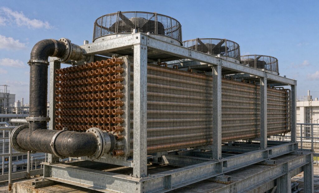
Air Cooled Condenser Sizing Starts With Heat Rejection, Not Refrigeration Capacity
An air cooled condenser sizing exercise almost always begins with the wrong number. The compressor, the evaporator coil and the expansion valve are all selected on refrigeration capacity in kW. The condenser is not. It has to reject the refrigeration capacity plus the heat the compressor adds to the refrigerant, and that second term is not a rounding error — at low evaporating temperature it can add 30 to 55% to the load.
Get that first number wrong and every downstream decision is wrong with it: the condenser runs at a higher condensing pressure, the compressor runs at a higher pressure ratio, and the plant pays for it in power on every operating hour of the year. This guide sets out the sizing sequence, the correction factors that turn a catalogue number into a site number, and the installation details that decide whether the unit ever delivers its rating.
Step 1: Calculate Total Heat Rejection
Total heat rejection (THR) equals the net refrigeration effect plus the heat of compression:
THR = refrigeration capacity × heat of compression factor
The factor depends on refrigerant, evaporating temperature and compressor type. Where the compressor manufacturer publishes it, use that figure; where it does not, a condenser supplier’s reference table is the next best source.
| Duty | Evaporating temperature | Heat of compression factor | Notes |
|---|---|---|---|
| Chilled storage, comfort cooling | 0 to +5 °C | 1.15–1.25 | Hermetic and semi-hermetic reciprocating |
| Medium temperature cold store | −10 °C | 1.20–1.35 | Depends on refrigerant and discharge temperature |
| Frozen storage | −25 to −30 °C | 1.30–1.45 | Suction-cooled semi-hermetic compressors sit at the upper end |
| Blast freezing | −40 °C and below | 1.40–1.55 | Two-stage or economised systems change the factor |
| Screw compressor, any duty | — | 1.25–1.40 | Confirm with oil cooling arrangement chosen |
Two refinements belong in the calculation. Open-drive compressors reject the motor heat separately, so it does not appear in THR. Screw packages with liquid injection oil cooling add an oil cooler duty that some designs route to the same condenser — check which, because it changes the load by a meaningful margin. Both points are cheap to resolve with the compressor supplier’s data and expensive to discover after a plant trips on high pressure in July.
Step 2: Fix the Design Temperature Difference
The condenser’s design temperature difference (TD) is simply the design condensing temperature minus the design ambient air temperature:
TD = condensing temperature − ambient temperature
For air-cooled equipment, the condensing temperature is set roughly 10–15 K above the summer design ambient, and the accepted practice varies by duty: a 10 K approach is common on medium-temperature systems, 8 K on low-temperature systems where the pressure ratio is already high, and 12–15 K where the designer is trading capital cost against energy. Whatever value is chosen, it must be applied at the summer peak ambient for the site, not the annual average. A condenser selected at 30 °C ambient will be short of capacity on the 40 °C afternoon that defines the plant’s worst day.
The consequence of the wrong choice is arithmetic, not opinion. Cap the TD at 10 K instead of 15 K and the required surface area rises by roughly half, because the capacity of a coil scales approximately with the temperature difference available. The larger coil then buys a lower condensing pressure, which lowers compressor power for the life of the plant.
Step 3: Correct the Catalogue Rating for the Site
Catalogue capacities are measured with clean coils, nominal voltage and unrestricted airflow at a stated ambient. Field conditions change all of that. The correction factors below are typical of air-cooled units with clean coils and free airflow, and should be replaced by the manufacturer’s own figures for the unit under review.
| Design ambient | Capacity factor | What to check |
|---|---|---|
| 25 °C | 1.08–1.12 | Fan cycling or speed control may be needed to hold condensing pressure |
| 30 °C | 1.03–1.06 | Close to the nominal catalogue point |
| 35 °C | 1.00 | Reference point used by many catalogues |
| 40 °C | 0.92–0.95 | Compare compressor current against nameplate |
| 45 °C | 0.85–0.89 | Verify the compressor envelope and all protection settings |
Three correction effects sit outside the ambient table and are frequently forgotten:
- Altitude. Air density falls about 1% per 100 m above sea level and heat rejection follows it. A site at 1,500 m loses roughly 4–6% of rated capacity.
- Recirculation. Warm discharge air returning to the coil face is far more damaging than altitude and far more common. A unit pushed against a wall, or facing another unit across a narrow gap, can lose 10% or more of effective capacity with no change to its nameplate.
- Fouling and fin damage. Dust, lint, pollen and airborne oil load the fin pack progressively; a partially blocked coil behaves like a smaller condenser. Specify the cleaning interval at the same time as the unit.
Step 4: Check the Compressor Envelope at Part Load and Worst Case
A condensing unit spends most of its life at part load, and it must survive its worst hour. Two checks close the loop:
- Worst-case summer. At the highest ambient the site will ever see, does the compressor stay inside its envelope, within current limits, and below the high-pressure cut-out with a margin?
- Part-load behaviour. How does the unit control condensing pressure as ambient falls? Fan cycling, fan speed control, flooding valves, variable setpoint or a condenser split into sections each behave differently — and the choice determines winter running cost as much as summer capacity.
Where the summer ambient is severe and the refrigeration load cannot be reduced, the practical options are a condenser with generous coil surface, an evaporative or adiabatic condenser that uses water only on peak days, or a water-cooled changeover. That last comparison is examined for a related duty in our guide to dry coolers versus cooling towers, and the same logic of ambient-limited capacity applies.
Air Cooled, Evaporative or Water Cooled?
| Criterion | Air cooled | Evaporative / adiabatic | Water cooled |
|---|---|---|---|
| Typical condensing temperature | Ambient + 10–15 K | Wet-bulb + 8–12 K | Water outlet + 5–8 K |
| Water consumption | None | Low — only on peak days in hybrid designs | High, plus cooling tower make-up |
| Seasonal stability | Poor — capacity tracks the weather | Good | Best |
| Power consumption | Highest at peak ambient | Moderate | Lowest at the compressor, plus tower and pump power |
| Footprint | Largest | Smaller | Smallest at the condenser |
| Maintenance | Coil cleaning only | Water treatment, scaling, fan and drift control | Water treatment, scaling, tower maintenance, freezing risk |
| Best fit | Water-scarce sites, cold and temperate climates, modular plants | Sites with a peak-day water budget and a load curve that peaks with the weather | Large plants with a reliable water supply and stable load |
For a cold store in a temperate climate, air-cooled equipment is normally the correct answer. For a large plant in a hot, water-scarce region, the choice is usually between a generously sized air-cooled unit and a hybrid adiabatic design — and the decision rests on peak-day performance, not on the annual average.
Installation Details That Decide Real Capacity
The gap between a rated and a delivered condenser is usually closed by site layout rather than by the coil.
- Respect the air-side clearances. Keep the inlet face clear of walls and other units so warm discharge air cannot short-circuit back into the coil. Where multiple units are installed in a row, roof upstands or discharge ducts are cheaper than lost capacity.
- Size refrigerant lines for the real run. Pressure drop in an undersized discharge or liquid line raises the condensing pressure and lowers the effective capacity; vertical risers need particular attention.
- Do not negate subcooling. Liquid line insulation, receiver sizing and the absence of avoidable pressure drop all preserve the subcooling the condenser produced.
- Plan the defrost and low-ambient strategy. Air-cooled condensers on low-temperature systems need a positive method of holding head pressure in winter, whether fan control, flooding or a variable setpoint.
- Specify the coil finish for the environment. Bare aluminium fins suit dry, clean sites; coastal, food-processing and washdown areas justify coated fins, copper or stainless construction, and the premium is repaid in service life. The same material logic is applied to our anti-corrosion condenser builds.
Specification Checklist for an Air Cooled Condenser
- Refrigerant and the net refrigeration capacity at the design operating point
- Design evaporating temperature and the required pulldown condition
- Heat of compression factor used, and its source
- Total heat rejection to be rejected, in kW
- Summer design ambient and the altitude of the site
- Design condensing temperature and the resulting temperature difference
- Correction factors applied for ambient, altitude and recirculation
- Available airflow clearance on the inlet and discharge faces
- Fan arrangement, motor type, and speed control or step control philosophy
- Low-ambient head pressure control method
- Coil materials: tube, fin, and any coating or electrophoretic treatment
- Refrigerant connection sizes, orientation and allowable pressure drop
- Subcooling required at the condenser outlet
- Noise limit at the nearest sensitive boundary, and the fan speed to meet it
- Electrical supply, protection rating and control interface
The Bottom Line
Size the condenser on total heat rejection at the site’s worst ambient, correct the rating for altitude and airflow before you compare bids, and treat the coil materials and clearances as part of the selection rather than as site details. A condenser that is 15% short on the hottest day raises condensing pressure all summer, and the compressor pays the bill.
Zhenggong Cooling and Heating Equipment manufactures dry-type, flooded and evaporative condensers, air-cooled heat exchangers and dry coolers together with plate and shell and tube units from a 35,000 m² facility in Shandong, China, holding D1/D2 pressure vessel certification with ISO 9001 and ISO 14001 systems, and exports to refrigeration and process customers worldwide. For a condenser selected against your refrigerant, load and summer ambient, send the operating conditions to the engineering team. The dry-type condenser range and the full product line-up cover the matched evaporator and chiller side of the same system.