
How Heat Exchanger Tube Failures Start
Tube failure is the leading cause of unplanned shell and tube heat exchanger outages, and it almost never begins with a hole. It begins with a wall thickness loss, a crack initiation site, or a vibration amplitude that nobody measured. By the time the unit fails a hydro test, the mechanism has usually been operating for months.
This guide sets out the four mechanisms that cause most tube failures, the inspection methods that detect each at an early stage, and a practical inspection interval you can defend to a maintenance budget.
The Four Dominant Failure Mechanisms
Corrosion and Wall Thinning
Uniform corrosion thins the tube wall at a predictable rate, which makes it the easiest mechanism to manage once you know the rate. Localised pitting and crevice corrosion are more dangerous because the average wall thickness stays healthy while a single pit penetrates. Pitting most often occurs under deposits, in stagnant zones, and on the tube outer surface where it contacts a tube sheet or baffle.
Stress corrosion cracking is a separate and faster problem. It appears on stainless tubes in chloride-bearing environments above roughly 60 °C, and on carbon steel in caustic or amine service. A cracked tube can fail completely with almost no measurable wall loss, which is why wall thickness surveys alone do not prove a unit is sound.
Erosion and Flow-Assisted Damage
Erosion is velocity-driven and concentrates at the tube inlet, where the flow enters at an angle from the channel head. It accelerates sharply once tube-side velocity passes the level the tube material can tolerate for the fluid in question. For water in carbon steel tubes, that threshold is often quoted around 2 to 3 m/s; for the same fluid with entrained solids, it drops much lower. A heat exchanger running above its design flow, or with a partially blocked tube, will erode its inlet ends first.
Vibration and Fatigue
Tubes vibrate in response to shell-side crossflow. Three failure patterns follow: tube-to-tube clashing where adjacent tubes wear against each other, tube-to-baffle fretting where the tube wears through at a baffle hole, and fatigue cracking at the tube sheet joint where the tube cannot flex. Vibration damage is distinctive because it is always localised and always at a structural contact point. It is also the failure you can predict and prevent with a proper flow analysis.
Fouling and Overheating
Deposits insulate the tube wall, so the metal runs hotter than the design assumed. On a fired or high-temperature unit that elevated wall temperature can push the tube into creep, causing bulging and eventual rupture. On a steam-heated unit, scale on the steam side raises the wall temperature and accelerates both corrosion and creep simultaneously.
Inspection Methods and What Each One Catches
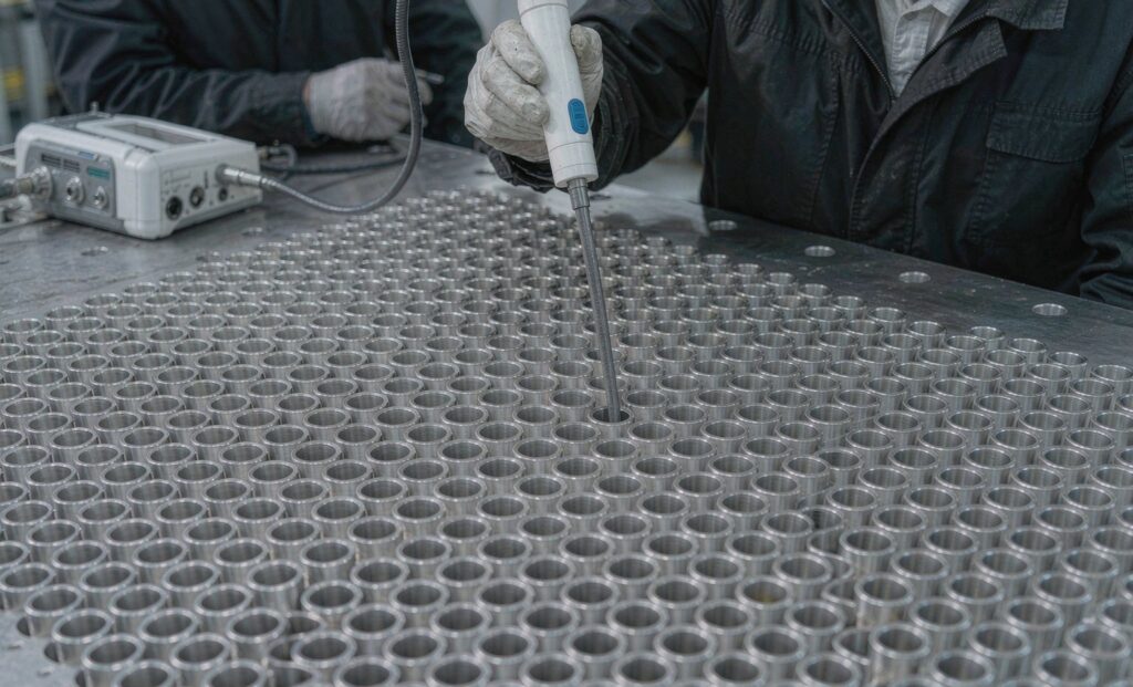
No single technique covers all four mechanisms. The table below maps each method to the failure it actually detects.
| Method | Detects | Blind to |
|---|---|---|
| Visual bore inspection (borescope) | Erosion at inlets, pitting, deposits, bulging | Outer surface condition, internal cracks |
| Eddy current testing | Wall loss, pitting, cracks in non-ferromagnetic tubes | Perforations behind tube sheet, ferromagnetic tube walls |
| Remote field eddy current | Wall loss in carbon steel and ferritic tubes | Very small pits |
| Hydrostatic pressure test | Through-wall perforations | Anything not yet through the wall |
| Helium leak test | Very small through-wall leaks and tube sheet joint leaks | Wall loss, cracks not yet through |
| Vibration analysis / flow study | Predicted tube vibration and fatigue risk | Corrosion mechanisms entirely |
A Step Checklist for Shutdown Inspection
- Record the last known tube-side and shell-side velocities at design flow.
- Remove the channel covers and borescope the first 200 mm of every tube on the inlet side.
- Note any tube that is discoloured relative to its neighbours — early fouling or overheating.
- Sample a statistically meaningful fraction of tubes by eddy current, weighted towards the hottest and dirtiest zones.
- Inspect baffle holes for polished rings, the signature of tube-to-baffle fretting.
- Check for gaps or witness marks between adjacent tubes — evidence of clashing.
- Examine tube sheet joints for circumferential cracking.
- Compare measured wall loss against the corrosion allowance in the design calculation.
- Log every reading against tube position so the next inspection shows a trend, not just a snapshot.
Setting an Inspection Interval You Can Defend
Inspection interval should follow the mechanism with the fastest rate, not the average. If your unit has a demonstrated corrosion rate of 0.1 mm per year and a 1.6 mm corrosion allowance, a four-year interval looks reasonable until you remember that pitting can penetrate ten times faster than uniform corrosion in a localised zone. A defensible approach is a first inspection at one third of the calculated life, then adjust the interval based on what you actually measure.
Retubing is often more economic than replacing a whole exchanger, and it lets you upgrade the tube material to match the mechanism you found. If you are seeing chloride stress cracking on 304 tubes, a move to a duplex or higher-alloy grade solves the mechanism rather than deferring it. Our guide to stainless shell and tube heat exchangers covers the material options, and our notes on heat exchanger fouling causes and prevention address the deposit side of the problem.
If your units are failing repeatedly on the same duty, the underlying cause is usually a design mismatch rather than a maintenance failure. Our engineering services include tube failure analysis and re-rate studies for existing units, and our applications by industry pages set out the typical duties where each failure mode concentrates.
Prevention Beats Inspection
Three design choices remove most tube failure risk at the outset. Keep velocities inside the material’s erosion threshold instead of pushing them up to save area. Add impingement plates or ferrules at tube inlets in any duty with entrained solids. And run a vibration analysis on any shell-side crossflow design before it is built, rather than after the first leak.
Zhenggong Cooling and Heating Equipment Co., Ltd manufactures shell and tube, plate and air-cooled heat exchangers at its 35,000 m² Shandong facility, holds D1/D2 pressure vessel certification and operates to ISO 9001 and ISO 14001. We can supply replacement bundles to the original tube sheet dimensions and advise on tube material selection for your specific mechanism. Contact us through our contact page with your failure history, or see our certification page for the inspection documentation provided with every unit.
Last updated: October 2026.
Source: TEMA Standards and ASME Boiler and Pressure Vessel Code Section VIII.