
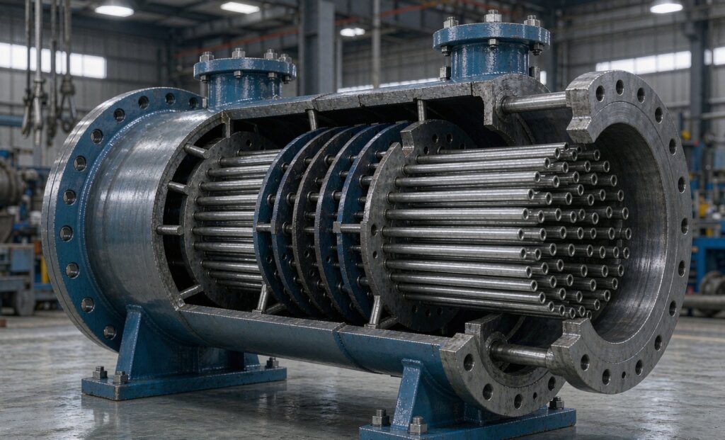
Why Baffle Spacing Decides Shell and Tube Performance
Baffle spacing is the single most under-specified number in most shell and tube heat exchanger enquiries. Buyers send flow rates, temperatures and a duty, then leave the internal geometry entirely to the supplier. That is a mistake, because baffle spacing controls the shell-side velocity, and shell-side velocity controls both the heat transfer coefficient and the pressure drop. Get it wrong and you either pay for a unit twice the size you needed or you buy a unit that cannot pass its design flow without tripping the pump.
In this guide we look at what baffle spacing actually does, how the shell-side Reynolds number responds to it, and how to specify a shell and tube heat exchanger so the thermal design and the hydraulic design agree with each other.
What Baffle Spacing Does to Shell-Side Flow
Segmental baffles force the shell-side fluid across the tube bundle in a zigzag path instead of letting it run straight down the shell. The distance between consecutive baffles is the baffle spacing, usually quoted as a fraction of the shell inside diameter. A tight spacing (say 0.2 of the shell diameter) means a short crossflow path and a high velocity for a given volumetric flow. A wide spacing (0.5 or more) means a long path and a low velocity.
That velocity matters more than most buyers expect. For turbulent flow on the shell side, the heat transfer coefficient roughly follows the velocity to the power of about 0.6 to 0.8, while pressure drop follows the velocity squared. So halving the spacing might raise the coefficient by 40 to 60 per cent, but it can multiply the pressure drop by four. The trade is never free, and it is rarely linear.
The Reynolds Number You Should Ask About
Ask your supplier for the calculated shell-side Reynolds number at design flow. Below roughly 2,000 the shell side is laminar and the coefficient collapses; you will need far more area for the same duty. Between 2,000 and 10,000 you are in transition, which is the awkward zone where correlations are least reliable and where a small fouling allowance swings the result. Above 10,000 you are properly turbulent and the design becomes predictable.
The practical consequence: if a supplier quotes a shell and tube exchanger that is suspiciously small and cheap, check the shell-side Reynolds number. A laminar or transitional design will meet the duty on paper at clean conditions and then fail once a normal fouling layer forms.
How to Specify Baffle Geometry Properly
Rather than accepting whatever the supplier chooses, put the constraints in the enquiry. The table below lists what to state and why it matters.
| Parameter to specify | Typical guidance | Why it matters |
|---|---|---|
| Baffle spacing range | 0.2 to 0.5 of shell ID | Sets shell-side velocity; below 0.2 the pressure drop becomes punitive, above 0.5 the coefficient drops off |
| Baffle cut | 20 to 25 per cent of shell ID for single segmental | Larger cuts reduce crossflow and create more window flow; smaller cuts raise pressure drop across the baffle tip |
| Maximum pressure drop | State it explicitly, both sides | Without a stated limit the thermal design will always win and the hydraulics will be ignored |
| Fouling resistance | Use a real TEMA-style allowance, not zero | A zero fouling allowance always passes the clean check and always fails in service |
| Minimum shell-side velocity | Above about 1 m/s where fouling is likely | Low velocity lets solids settle and accelerates fouling |
| Baffle type | Single segmental for clean service, rod or twisted tube for fouling service | Segmental baffles create dead zones behind the baffle that trap deposits |
A Step Checklist for the Enquiry
- State the duty, both flow rates, and all four terminal temperatures.
- State the maximum allowable pressure drop on each side, in kPa, as a hard limit.
- State the design fouling resistance for each stream, drawn from the fluids involved.
- Ask for the calculated shell-side and tube-side Reynolds numbers at design flow.
- Ask for the baffle spacing, cut and type to be shown on the outline drawing.
- Ask what the predicted duty is at the fouled condition, not just clean.
- Ask for the minimum shell-side velocity at turndown, if the plant will ever run below design.
Where Baffle Spacing Interacts With Fouling
Fouling and baffle geometry are not independent problems. Segmental baffles leave a low-velocity wake behind each baffle plate, and that wake is exactly where suspended solids settle out. A design with tight baffle spacing raises the bulk velocity but also creates more baffles, and therefore more wakes. In dirty service this is why baffle spacing alone cannot fix a fouling problem, and why rod baffles or a helical baffle arrangement is often the better answer.
If your fluid carries fibres, scale-forming salts or biological growth, decide up front whether you want a cleanable design. A shell and tube exchanger with wide baffle spacing and a removable bundle is cleanable by hydrojetting. A brazed plate unit with narrow channels may have better thermal performance but cannot be mechanically cleaned at all. That trade should be settled before the hydraulics are optimised, because it constrains which baffle arrangements are available to you.
Reading a Thermal Design Report
When the supplier returns a calculation, look for the baffle spacing as a dimension on the drawing rather than a note. If it appears only as text and does not match the outline, treat the design as unverified. Then check the pressure drop line for each side against the limit you set. Two numbers tell you most of the story: the shell-side velocity and the shell-side pressure drop. If the velocity is high and the coefficient is still low, the baffle cut is probably too large. If the velocity is low, the spacing is too wide and the unit will foul.
For a wider comparison of construction types before you commit to a baffled shell and tube design, our guide to shell and tube versus plate heat exchangers sets out where each belongs. If your application is a clean, high-duty process duty, also see our notes on stainless shell and tube heat exchangers for the material and construction choices available.
The Short Version
Baffle spacing is a design decision that belongs to you, not to the supplier. Specify a spacing range, a baffle cut, a hard pressure drop limit and a real fouling resistance, and ask for the shell-side Reynolds number. Those five numbers turn a vague enquiry into a design you can compare between suppliers on equal terms.
Zhenggong Cooling and Heating Equipment Co., Ltd manufactures shell and tube, plate and air-cooled heat exchangers at its 35,000 m² facility in Shandong, China, and holds D1/D2 pressure vessel certification alongside ISO 9001 and ISO 14001. Send us the duty, the limits and the fluids, and we will return a thermal design with the baffle geometry shown on the drawing. Reach out through our contact page for a quote, or review our certification page for the documentation available with each unit.
Last updated: October 2026.
Source: TEMA Standards, Shell and Tube Heat Exchanger Manufacturers Association.