
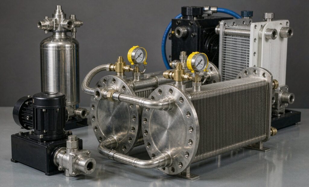
When Oil Temperature Becomes the Constraint on Machine Output
Hydraulic systems convert a large fraction of their input power into heat, and that heat has nowhere to go except the oil. Left uncooled, a hydraulic circuit stabilises at whatever temperature balances heat generation against natural convection from the reservoir and pipework — and on anything larger than a small power pack, that equilibrium sits well above the 45–55 °C window where hydraulic oil performs as designed.
Above that window three things happen simultaneously. Viscosity falls, which thins the lubricating film in pumps and motors and accelerates wear. Oxidation rates roughly double for every 10 °C rise, shortening fluid life and generating varnish and sludge. Seals harden and take a permanent set, and leakage past worn clearances rises. The result is a machine that runs hot, loses positioning accuracy, and consumes pumps and oil at an accelerating rate.
Specifying a hydraulic oil cooler correctly is therefore less about thermal performance than about protecting the fluid. This guide covers heat load estimation, air-cooled versus water-cooled selection, sizing against both hot-running and cold-start conditions, circuit integration, and the maintenance that keeps a cooler working.
Estimating the Heat Load
The first number to establish is how much heat the circuit actually generates. There are three approaches, in increasing order of accuracy:
Rule-of-thumb from installed power
In well-designed industrial systems, 20–30% of the installed prime-mover power is converted to heat. For a 75 kW power pack, that implies 15–22 kW to reject. This is a reasonable starting point for a new design with no operating data, but it is a wide band and it should never be the final basis for selection.
Calculation from circuit losses
Sum the pressure drops across relief valves, throttle valves, flow controls, fittings and the pipework itself, multiply by the flow through each element, and add the mechanical and volumetric losses of pumps and motors. This gives a defensible number for a system that is fully defined on paper.
Measurement on the existing machine
The most reliable method, and the one to use on any retrofit. Run the machine to thermal equilibrium with no cooling, record the oil temperature rise over a known period, and back-calculate:
Q = (m × cp × ΔT) / t
Where m is the mass of oil in the reservoir, cp is the oil’s specific heat capacity (roughly 1.8–2.1 kJ/kg·K for mineral hydraulic oils), and ΔT is the temperature rise over time t. Once the machine has stabilised, this measurement captures every loss mechanism in the circuit — including the ones the paper calculation forgot.
With the residual load known, apply a margin. For sizing a cooler, a 20–30% allowance covers fouling, ambient variation and future load growth. Do not inflate it further to cover an unknown heat load: if the load is unknown, measure it. An arbitrarily oversized cooler wastes money, occupies space, and in some circuits causes overcooling that drives viscosity too high at part load.
| Application | Typical heat load | Sizing margin | Notes |
|---|---|---|---|
| Light industrial power pack | 20–25% of drive power | 1.2× | Controlled indoor environment |
| Standard industrial machine | 25–30% of drive power | 1.35× | Normal duty, moderate ambient variation |
| Heavy or mobile equipment | 30%+ of drive power | 1.5× | Severe duty, outdoor, high summer ambient |
| Intermittent press or injection cycle | Peak, not average, governs | 1.35–1.5× | Reservoir thermal mass smooths short peaks only |
Air-Cooled or Water-Cooled?
The choice is driven by what cooling medium is available, how dirty it is, and what temperature the oil must reach.
| Parameter | Air-cooled (fan) | Water-cooled (shell and tube) | Water-cooled (plate) |
|---|---|---|---|
| Typical U-value (W/m²K) | 25–40 | 450–850 | 850–1,400 |
| Approach to coolant inlet | 15–25 K | 10–15 K | 5–10 K |
| Footprint for equal duty | Largest | Moderate | Smallest |
| Water consumption | None | Yes | Yes |
| Fouling tolerance | Fin-side dust and oil mist | Good — straight tubes, removable bundle | Poor — narrow channels block easily |
| Mechanical cleaning | Fins blown or washed | Bundle withdrawn, tubes rodded | Not possible — chemical CIP only |
| Noise | Fan noise, significant at large sizes | None | None |
| Best fit | Mobile plant, water-scarce sites, remote installations | Dirty or hard cooling water, high fouling risk | Clean closed-loop water or water-glycol |
The decisive factor is usually cooling water quality. A plate cooler offers the highest U-value and the smallest footprint, but its narrow channels foul rapidly if the water carries hardness, suspended solids or biological growth — and there is no way to clean them mechanically. Where the water is dirty, fibrous or scale-forming, a shell-and-tube unit with a removable bundle is the correct choice despite the larger size, because an operator can pull the bundle and rod the tubes. This is the same logic that governs any stainless shell and tube heat exchanger on a fouling duty.
On a clean closed-loop water or water-glycol circuit, a plate cooler is the better answer: more heat transfer per unit of space, closer approach temperatures, and a lower oil volume in the circuit. Where the process prohibits copper, a nickel-brazed plate unit replaces the copper-brazed standard.
The Sizing Calculation
Once the load is known, the required surface area follows from the logarithmic mean temperature difference, or LMTD:
Q = U × A × LMTD
And the LMTD for a counter-flow arrangement:
LMTD = (ΔT₁ − ΔT₂) / ln(ΔT₁ / ΔT₂)
where ΔT₁ is the temperature difference at one end and ΔT₂ at the other. The counter-flow configuration is assumed because it gives the greatest driving force and allows the closest approach between the oil outlet and the coolant inlet.
The sensitivity here is severe and worth internalising: because the driving force is proportional to the temperature difference, halving the available differential roughly doubles the required surface area. That makes the coolant inlet temperature one of the most sensitive inputs in the whole calculation — often more so than a modest change in flow rate.
A worked example. An ISO VG 46 oil enters a cooler at 55 °C and must leave at 47 °C, flowing at 120 L/min. Taking oil density as 850 kg/m³ and specific heat as 2.0 kJ/kg·K:
- Mass flow: 120 L/min = 0.002 m³/s × 850 kg/m³ = 1.70 kg/s
- Heat load: 1.70 × 2.0 × 8 K = 27.2 kW
- With a 15–25% margin, size for 31–34 kW
For the coolant side, if water enters at 30 °C and is allowed to leave at 35 °C, the energy balance gives the required water flow:
- Water flow: 27.2 / (4.18 × 5) = 1.30 kg/s ≈ 4.7 m³/h
Now check the LMTD for a counter-flow arrangement with oil 55 → 47 °C and water 30 → 35 °C:
- ΔT₁ = 55 − 35 = 20 K
- ΔT₂ = 47 − 30 = 17 K
- LMTD = (20 − 17) / ln(20/17) = 3 / 0.1625 ≈ 18.5 K
At a plate cooler U-value of 1,000 W/m²K, the required area is 27,200 / (1,000 × 18.5) ≈ 1.47 m², before the fouling allowance is added. With a 25% margin, specify approximately 1.8 m².
Note how much the answer moves if the cooling water is warmer. At 35 °C inlet instead of 30 °C, the LMTD falls to about 13.5 K and the required area rises by nearly 40%. Coolant temperature is the parameter to pin down precisely before quoting.
Cold-Start Is the Case That Breaks Coolers
A cooler that performs perfectly at 47 °C operating temperature can be destroyed by a start-up at 10 °C. At low temperature the oil is far more viscous, the pressure drop across a narrow-channel cooler rises sharply, and the resulting pressure spike can deform plates or rupture a brazed core.
The pressure drop must therefore be checked at two conditions: normal operating viscosity, and the cold-start viscosity the system will actually see. For an ISO VG 46 mineral oil at 10 °C, viscosity is roughly ten times its value at 50 °C — pressure drop through the cooler rises by a similar order. Three protections are standard:
- A bypass relief valve across the cooler, set between 2 and 6 bar, so the cooler is never exposed to full cold-start pressure
- A thermostatic control valve that diverts oil through the cooler only once operating temperature is reached, which also prevents overcooling at part load
- Fan or pump control that modulates cooling to demand rather than running continuously
All three should be part of the specified package, not added later.
Circuit Integration: Return Line or Offline Loop
Where the cooler sits in the circuit determines both its duty and its service life.
Return-line installation
The cooler sits in the line returning oil from the actuators to the reservoir. It uses the existing circuit flow and needs no auxiliary pump. The drawback is exposure to the pressure spikes and hydraulic shocks generated by directional control valves — which is exactly why a bypass relief valve is mandatory on this arrangement.
Offline (auxiliary) cooling circuit
A dedicated motor-driven pump draws oil from the reservoir, passes it through a filter and the cooler, and returns it to the tank. This gives constant flow independent of the machine cycle, protects the cooler from pressure spikes entirely, and allows cooling to be combined with fine filtration. The cost is an extra pump-motor set, additional space, and higher initial investment.
For high-value machines with continuous duty, or where the machine cycle produces violent pressure spikes, the offline arrangement is usually worth the premium. For mobile equipment, return-line installation with proper protection is the practical norm.
Maintenance That Keeps the Duty
Fouling of the heat transfer surface is the single largest cause of lost cooling capacity. The maintenance regime differs by cooler type.
- Air-cooled cores: dust, oil mist and airborne debris accumulate on the fins and form an insulating layer that also restricts airflow. Clean periodically with compressed air blown against the fan’s airflow direction, or with low-pressure washing and a suitable degreaser. Check that the fan blades and guard are clean too.
- Water-cooled tubes: limescale, algae and mineral deposits build inside the tubes, reducing flow area and insulating the surface. Counter-flow chemical descaling restores the internal finish and recovers the original performance.
- Thermostatic valves and temperature sensors: verify the thermostatic element operates at its set point and calibrate thermostats and PT100 sensors periodically. A failed thermostatic valve that never opens will overheat the system; one stuck open will overcool it.
- Monitor the temperature approach. A rising oil-outlet temperature at unchanged load and coolant temperature is the earliest reliable indicator of fouling. Trend it.
Specification Checklist
- Heat load to be rejected, in kW, and how it was established
- Sizing margin applied and the reasoning behind it
- Oil type and ISO viscosity grade
- Oil flow rate through the cooler, in L/min, at operating temperature
- Required oil outlet temperature, and the reservoir operating setpoint
- Coolant: air with design summer ambient, or water with inlet temperature and available flow
- Coolant quality — hardness, suspended solids, biological growth, chloride content
- Maximum allowable oil-side pressure drop at operating viscosity
- Cold-start viscosity and the expected pressure drop at that condition
- System operating pressure and peak pressure, including shock loading
- Materials: core or tubes, shell, tubesheet, and seal material compatible with the oil
- Protection: bypass relief valve setting, thermostatic valve, fan or pump control
- Installation position: return line or offline loop, and the available space envelope
- Noise limits where the unit is near occupied areas
- Cleaning method and the access required
The Bottom Line
A hydraulic oil cooler is a small fraction of the cost of the machine it protects, and the failure mode when it is underspecified or fouled is not a tripped alarm — it is accelerated wear that shows up as pump replacement, seal failure and fluid degradation months or years later. Size on a measured heat load, size for the worst ambient and coolant conditions rather than the annual average, protect the cooler from cold-start pressure, and trend the temperature approach so fouling is caught before it costs a production shift.
Zhenggong Cooling and Heating Equipment manufactures plate, brazed, shell and tube and air-cooled heat exchangers from a 35,000 m² facility in Shandong, China, holding D1/D2 pressure vessel certification and ISO 9001 plus ISO 14001 systems, and exports to industrial hydraulic and process cooling customers worldwide. For a cooler selected against your oil grade, flow and worst-case coolant temperature, send the operating conditions to the engineering team. You can also see how the same selection logic applies to a different heat rejection problem in our comparison of dry coolers and cooling towers.